Schematics
Section
5-6 AB46 Work Platform
First page on foldout
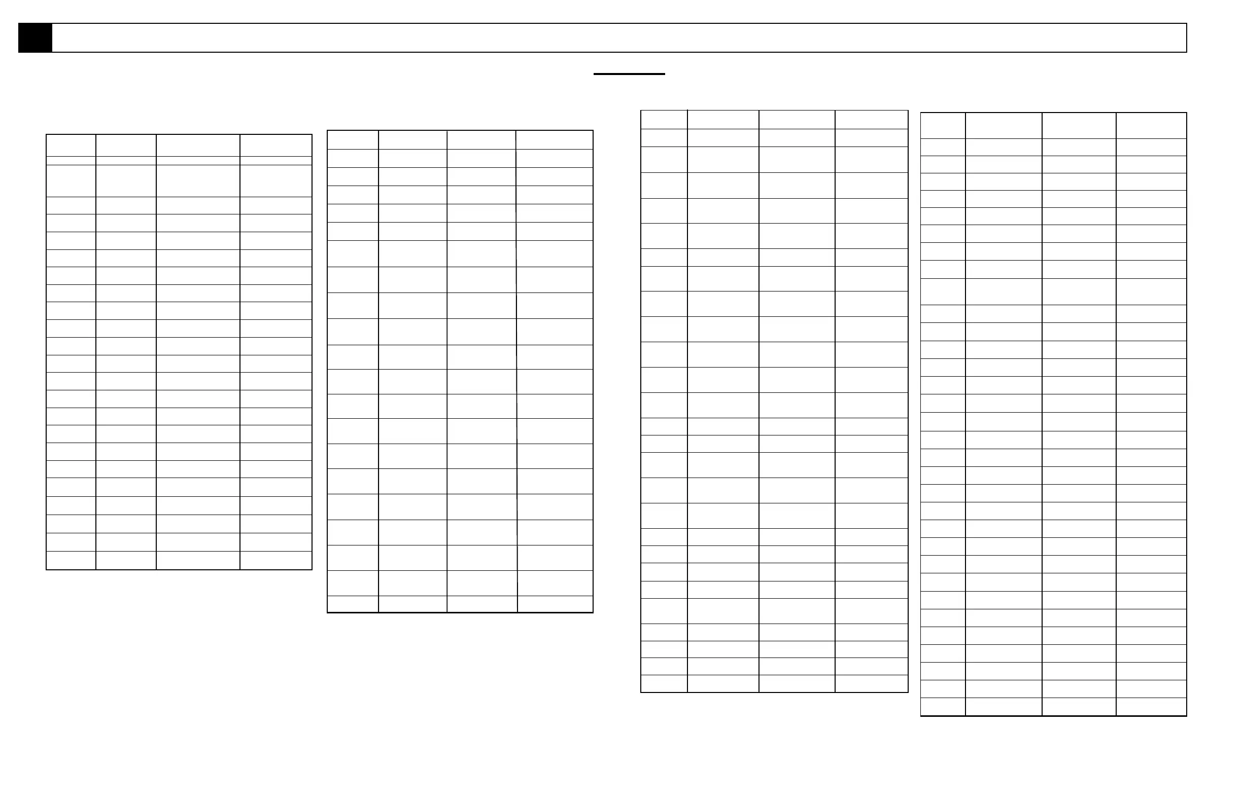
5.1 Electrical Schematics
Table 5-3: (cont.)
Table 5-3: Electrical Schematic Legend, Diesel Model - 068341-003
REFERENCE
DESIGNATION NAME FUNCTION LOCATION
ALM 1 Horn Warning sound Front of chassis
ALM 2 Alarm, Tilt Provides warning sound Upper control box,
when slope of machine exterior upper left side.
excedes 3
o
side to side,
or fore and aft.
CONT1 Controller Controls operating speed Upper control box
of various functions
D1 Diode Supplies power to Lower control box
throttle relay
D2 Diode Supplies power to Lower control box
throttle relay
D3 Diode Supplies power to Lower control box
throttle relay
D4 Diode Spike protection Joystick handle
diode
D5 Diode Supplies power to Upper control box
speed controller CONT1
D6 Diode Supplies power to Upper control box
speed controller CONT1
D7 Diode Supplies power to Upper control box
speed controller CONT1
D8 Diode Supplies power to Upper control box
speed controller CONT1
D9 Diode Supplies power to high Upper control box
flow solenoid
D10 Diode Supplies power to high Upper control box
flow solenoid
D11 Diode Supplies power to boom Upper control box
elevate speed relay
D12 Diode Supplies power to boom Upper control box
elevate speed relay
D13 Diode Provides power to Lower control box
throttle relay
D14 Diode Provides power to Lower control box
tilt alarm
D15 Diode Provides power to Lower control box
throttle relay
D16 Diode Provides power to Lower control box
brake solenoid
D17 Diode Power to tilt Lower control box
alarm ALM2
D18 Diode Power to Lower control box
engine relay
D19 Diode Power to Lower control box
throttle relay
D20 Diode Power to Engine Compartment
Engine
REFERENCE
DESIGNATION NAME FUNCTION LOCATION
FU1 Fuse Engine Power Lower Control box
10 AMP
FU2 Fuse Emergency Stop Lower Control box
25 AMP
FU3 Fuse Chassis Controls Lower Control box
10 AMP
FU4 Fuse Platform Controls Upper Control box
10 AMP
L1 Tilt Light Lights when machine Upper Control box
is in tilt condition
PMP1 Drive Pump Hydraulic Drive Chassis
Power
R1 Relay Power to up Relay Panel
trim solenoid
R2 Relay Power to down Lower Control box
trim solenoid
R3 Relay Power to up Lower Control box
jib solenoid
R4 Relay Power to down Lower Control box
jib solenoid
R5 Relay Power to up Lower Control box
boom solenoid
R6 Relay Power to down Lower Control box
boom solenoid
R7 Relay Power to extend Lower Control box
boom solenoid
R8 Relay Power to retract Lower Control box
boom solenoid
R9 Relay Power to up Upper Control box
riser solenoid
R10 Relay Power to down Upper Control box
riser solenoid
R11 Relay Power to cage Upper Control box
Right Solenoid
R12 Relay Power to cage Upper Control box
left solenoid
R13 Relay Power to turret Relay Panel
right solenoid
R14 Relay Power to turret Relay Panel
left solenoid
REFERENCE
DESIGNATION NAME FUNCTION LOCATION
R15 Glow Plug Relay Power to Glow Plug Lower Control box
R16 Brake Relay Power to Brake Lower Control box
Solenoid
R17 Engine Throttle Power to Engine Lower Control box
Relay Throttle Relay
R18 Low Tilt Relay Disenables Drive Lower Control box
Functions
R19 Engine Relay Enables Engine Lower Control box
to operate
R20 Power Relay Power to Controller Lower Control box
R21 Down Relay Power to Hydraulic Lower Control box
Pump
R22 Boom Disconnect Power to Upper Upper Control box
Relay Controller
R23 Boom Elevate Speed Power to Speed Upper Control box
Relay Controller
R24 Turret Drive Relay Power to Turret Upper Control box
Rotate Solenoid
R25 Drive Enable Relay Power to Upper Upper Control box
Control box
R26 Differential Lock Activates Differential Lower Control box
Relay Lock
RES1 Resistor Speed control Joystick control
S1 Trim Switch, Power to Trim Lower Control box
(two) Solenoid Upper Control box
S2 Jib Switch, Power to Jib Lower Control box
(two) Solenoid Upper Control box
S3 Boom Elevate Switch Power to Boom Lower Control box
(two) Lift Solenoid Upper Control box
S4 Boom Extend Switch Power to Boom Lower Control box
(two) Extend Solenoid Upper Control box
S5 Riser Switch Power to Riser Lower Control box
(two) Solenoid Upper Control box
S6 Cage Switch Power to Cage Lower Control box
(two) Rotate Solenoid Upper Control box
S7 Turret Switch Power to Turret Lower Conrtol box
(two) Rotate Solenoid Upper Control box
S8 Differential Lock Locks Differential Joystick
Switch
S9 Choke/Glowplug Actuates Upper Control box
Switch Choke/Glowplug
S10 Steer Switch Power to left steer Upper control box,
and right steer relays top of joystick.
S11 Oil Pressure Stops Engine if Engine
Switch low pressure
S12 Engine Start Switch Starts Engine Lower control box
S13 Platform/Chassis Supplies power to Lower control box
Switch Platform/Chassis
REFERENCE
DESIGNATION NAME FUNCTION LOCATION
S14 Down Limit Switch Controls travel speed Turret at boom
Slow/Fast attachment
S15 Chassis Emergency Emergency Stop Lower control box
Stop Switch
S16 Choke/Glow Plug Actuates Choke/Glow Lower control box
Switch Plug
S17 Foot Switch Enables operation from Floor of platform
platform
S18 Platform Emergency Emergency Stop Platform control box
Stop Switch
S19 Platform Key Switch Enables operation from Platform control box
platform
S20 Horn Switch Sounds horn Platform control Box
S21 Boom Extend Drive Controls travel speed On Boom
Interlock Slow/Fast
SNSR Level Sensor Provides power to cutout Control module.
relay when machine is
level.
SOL1 Trim UP Solenoid. Controls lift valve. Right side of manifold
SOL2 Trim Down Solenoid. Controls lift valve. Right side of manifold
SOL3 Jib Up Solenoid. Controls lift valve. Right side of manifold
SOL4 Jib Down Solenoid. Controls lift valve. Right side of manifold
SOL5 Boom Up Solenoid. Controls lift valve. Right side of manifold
SOL6 Boom Down Solenoid. Controls lift valve. Right side of manifold
SOL7 Boom Extend Solenoid Controls reverse valve. Right side of manifold
SOL8 Boom Retract Solenoid. Controls lift valve. Right side of manifold
SOL9 Riser Up Solenoid. Controls lift valve. Right side of manifold
SOL10 Riser Down Solenoid Controls series / parallel Right side of manifold
valves.
SOL11 Cage Right Solenoid. Controls lift valve. Right side of manifold
SOL12 Cage Left Solenoid Controls down valve. Right side of manifold
SOL13 Turret Right Solenoid Controls steer valve when Right side of manifold
steering right.
SOL14 TurretLeft Solenoid Controls steer valve when Right side of manifold
steering left.
SOL15 Steer Right Solenoid Controls engine throttle. Right side of manifold
SOL16 Steer LeftSolenoid Controls engine choke. Right side of manifold
SOL17 Low Flow Controls lift valve. Right side of manifold,
SOL18 High Flow Controls lift valve. Right side of manifold,
SOL19 Engine Run Allows Engine to Engine Compartment
Solenoid Run
SOL20 Engine Throttle Controls Engine Engine Compartment
Solenoid Throttle
SOL21 Brake Solenoid Actuates Brakes Drive Valve Block
SOL22 Differential Lock Controls Differential Drive Valve Block
Solenoid Lock
SOL23 Bypass Solenoid Allows oil bypass Drive Valve Block
to tank
5.1
 Loading...