Section
5-14 AB46 Work Platform
Schematics
5.2
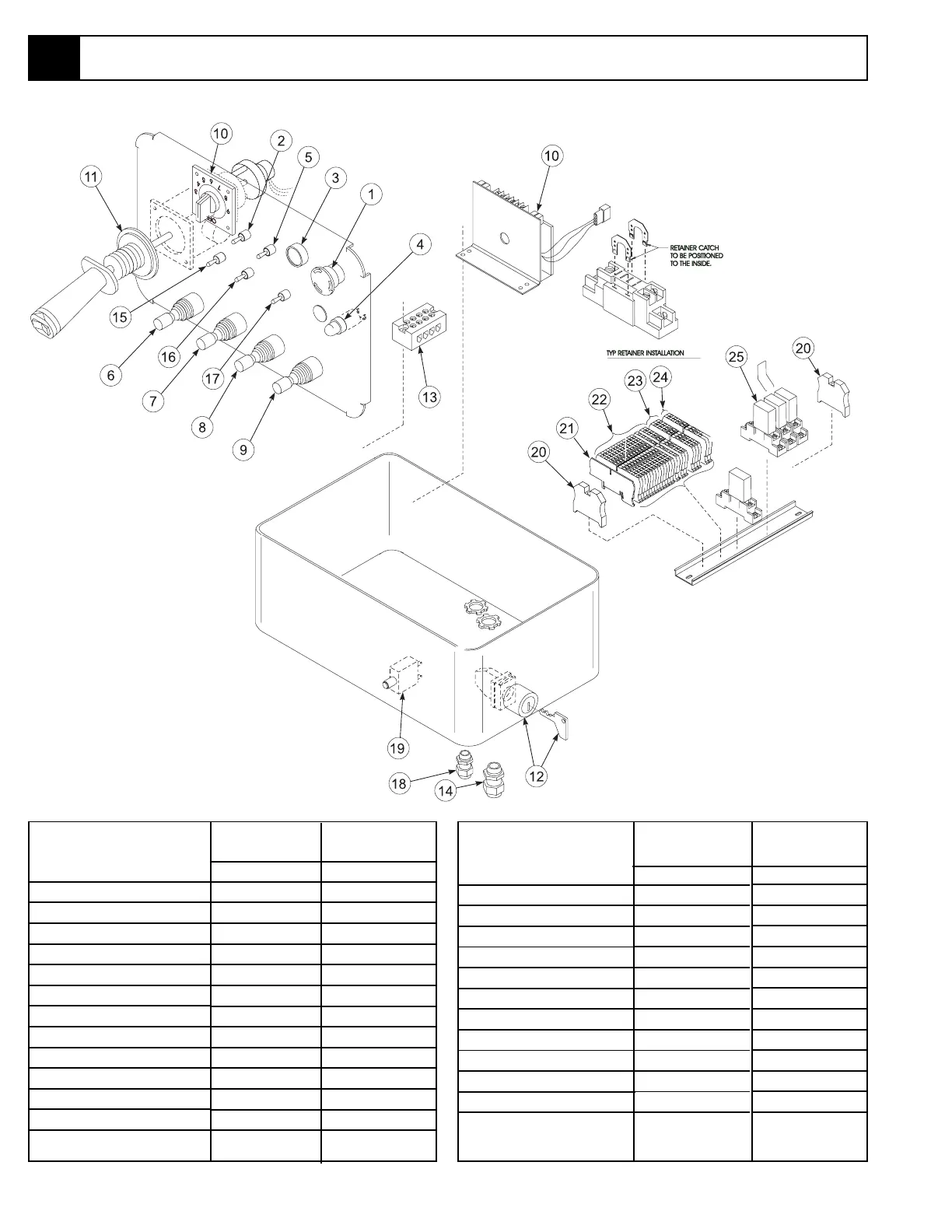
5.5 Upper Control Box Component Location
1. Emergency Stop Button
2. LP/Gas Switch
3. Horn
4. Out of Level Lamp
5. Switch, Choke/Glow Plug
6. Switch, Jib Control
7. Switch, Boom Extend
8. Switch, Upper Boom
9. Switch, Riser Control
10. Rheostat, Controller
11. Joystick
12. Key Switch/Engine Start
13. Terminal Strip
14. Cable Connector, 3/4
15. Switch, Platform Level
16. Switch, Platform Rotate
17. Switch, Turret Rotate
18. Cable Connector, 1/2
19. Circuit Breaker, 10 amp
20. Terminal End
21. End Cap, Contact Block
22. Terminal Block, Tan
23. Terminal Block, Blue
24. Terminal Block, Orange
25. Relay, SPDT, 48 Volt
Gas Model
X
X
X
X
X
X
X
X
X
X
X
X
Diesel Model
X
X
X
X
X
X
X
X
X
X
X
X
Figure 5-9: Upper Controller
Table 5-5: Upper Controller Components
Gas Model
X
X
X
X
X
X
X
X
X
X
X
X
X
Diesel Model
X
X
X
X
X
X
X
X
X
X
X
X
5.5