Section
3-18 AB46 Work Platform
Maintenance
7. Turn hub over so small end points down. Using
bearing cone pressing tool, press bearing cone onto
output shaft. Rotate hub while pressing bearing.
Stop pressing when hub starts to resist rotating.
8. Place spacer onto output shaft so it rests on top of
bearing cone. Using retaining ring pliers, place
retaining ring to make sure it is seated.
9. Hit the end of output shaft once or twice with a soft
face hammer. Turn the shaft in both clockwise and
counter clockwise directions while hitting. This will
seat the bearing cone against the spacer and retain-
ing ring allowing necessary endplay in the hub-shaft
sub-assembly.
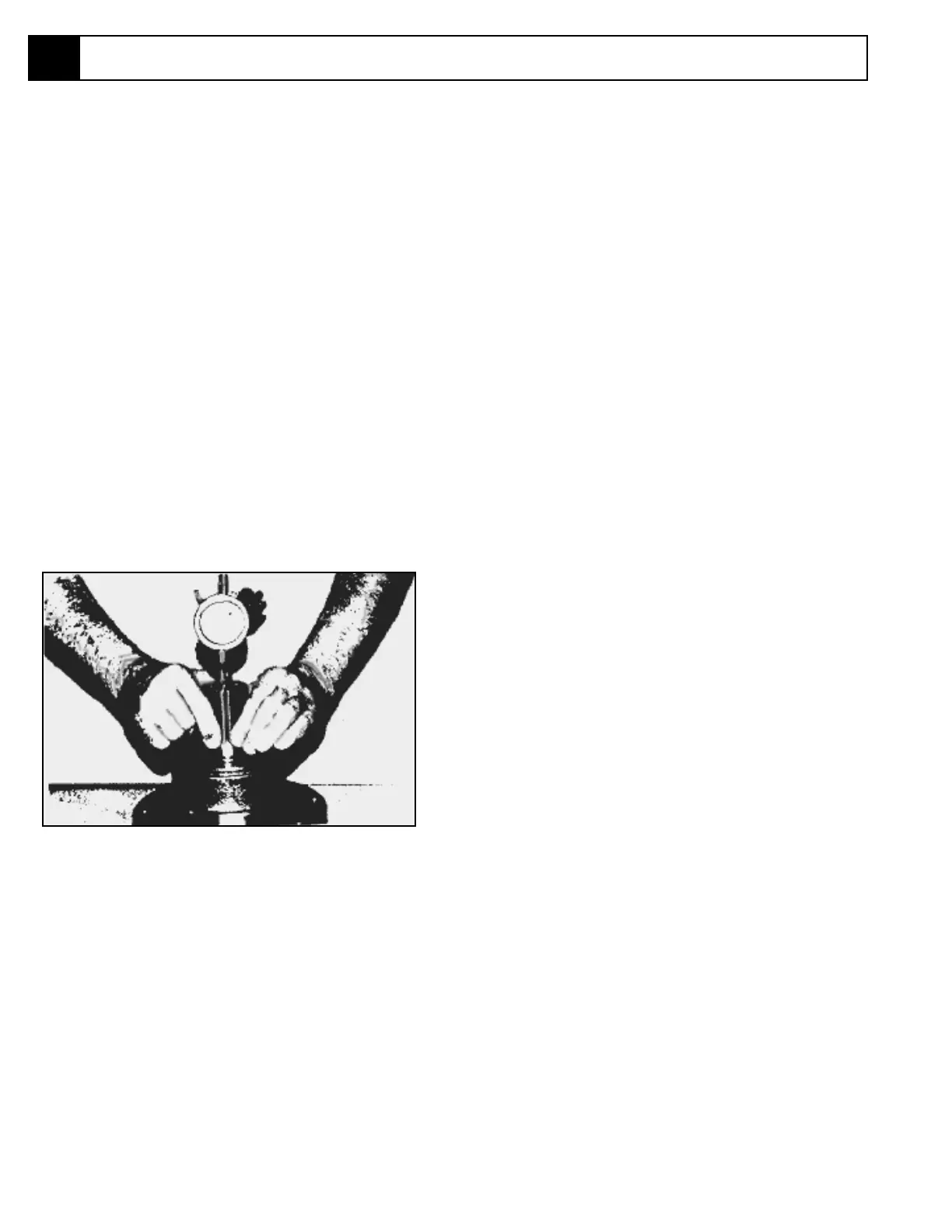
10. Turn hub over so it rests on large end. Measure
endplay in hub-shaft sub-assembly. Follow steps a-c.
a. Mount a dial indicator on hub . Locate the dial
rod on top of output shaft.
b. Lift up on output shaft until the needle on the
dial stops moving.
c. Read the dial. Reading should be no greater
than .008 in.
- If dial reads less than .008 in. continue on to step
11.
- If dial reads more than .008 in. repeat step 8-15 of
"DISASSEMBLY" section.
d. Remove spacer and replace it with thicker
spacer (SK91 068570-011).
e. Repeat steps 7-10 and remeasure end play.
11. Apply a light coat of "Never Seize" to the pipe plugs
and install into pipe plug holes in hub.
NOTE: Leave hole for 90° fitting open.
Torque Hub Seal Replacement
(Continued)
3.13
MAIN ASSEMBLY
1. Position hub on its output shaft so that hubs small
diameter end points down.
2. Using a marker, mark the four shoulder bolt holes in
hub.
3. Grease "O" ring and place in counterbore in hub.
NOTE: "O" rings may be stretched or squeezed
together in order to fit exactly in counterbore.
4. Oil all exposed surfaces inside hub. Oil carrier sub-
assembly.
5. Place carrier sub-assembly, with spline connections
down, into mesh with output shaft.
6. Place ring gear, with squared shoulder down, into
mesh with the planet gears of the carrier sub-
assembly. Make sure that marked shoulder bolt hole
on ring gear aligns with any of the marked shoulder
bolt holes on the hub. "X" mark should be on the
cover side of ring gear.
7. Start one half of retaining ring into groove inside
input gear. Use a soft punch to press the remaining
half of the retaining ring into the groove.
8. Insert input gear, with large diameter end down,
into mesh with planet gears.
9. Place large thrust washer over input gear so it rests
on carrier housing. Oil all exposed surfaces inside
hub.
10. Grease "O" ring and place into counterbore of cover.
NOTE: "O" rings may be stretched or squeezed
together in order to fit exactly in counterbore.
11. Place cover on top of ring gear so the fill hole will be
at top of hub when it is installed.
12. Install four shoulder bolts into shoulder bolt holes
and tighten.
13. Install eight cap screws in remaining holes and
tighten.
14. Apply 23-27 ft. lbs. of torque to all bolts.
15. Apply a light coat of "Never Seize" to both pipe
plugs and install into the two holes in cover.
16. Roll test the unit in both clockwise and counter-
clockwise directions. Turn hub nine full revolutions
in each direction.
17. Leak test the hub at Five PSI for two to three min-
utes.
Figure 3-18: Measuring Hub End Play