Section
5-16 AB46 Work Platform
Schematics
5.6 5.3
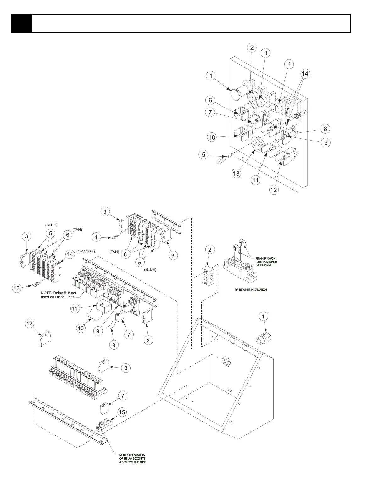
5.6 Lower Control Box Component Location
Figure 5-12: Lower Control Box Cover
Figure 5-13: Terminal Strip, Relay Identification
1. Cord Grip, 3/4"
2. Terminal Strip (120VAC)
3. End Block
4. Jumper, 2 pin
5. Terminal Block (blue)
6. Terminal Block (tan)
7. Relay, SPDT
8. Retainer Clip, 1 pole
9. Socket, Four Relay
10. Retainer Clip, 4 pole
11. Relay, 12 VDC, 4 pole
12. End Block, Terminal
13. Jumper, 3 pin
14. Terminal Block (orange)
15. Socket, Single Relay
Table 5-6: Lower Controller Components
1. Emergency Stop Button
2. Engine Start Button
3. Choke/Glow Plug
4. Key Switch
5. Fuse (25A)
6. Riser Switch
7. Boom Raise Switch
8. Boom Extend Switch
9. Jib Extend Switch
10. Turret Rotate
11. Cage Rotate Switch
12. Cage Level Switch
13. Hour Meter
14. Circuit Breaker