Electric Section 4 - Schematics
Page 4-2 114101-000 X26 Ultra Narrow - Service Manual
4-1 E
LECTRIC
Legend:
066769-020 Electric Schematic
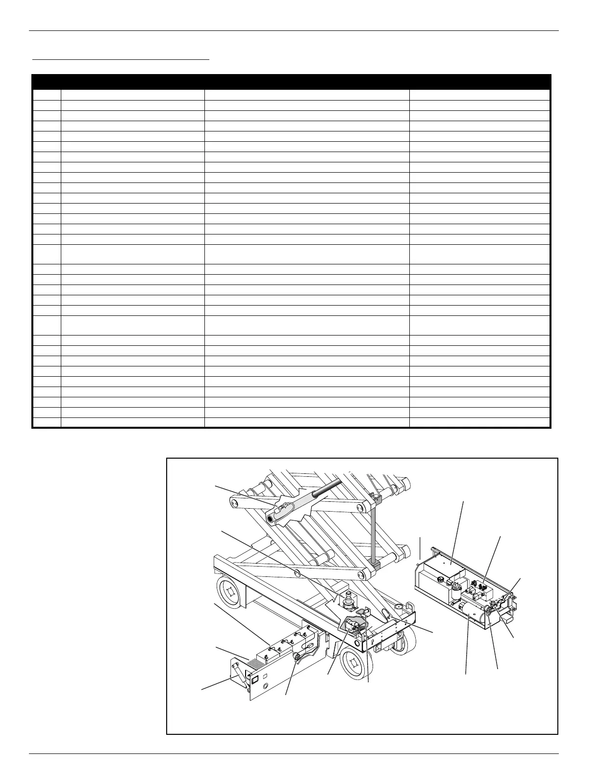
Figure 4-1:
Electric Components Locations
Reference
Number
Name Function Location
ALM Alarm Provides warning sound Control Module
BAT Battery Pack Power source for the machine Power Module
CHG Battery Charger Charges the battery pack Power Module
F1 5 AMP Circuit Breaker Electrical overload protection Chassis Controls
F2 175 AMP Fuse Overload protection for the electric motor Control Module
HM Hour Meter Shows how many hours the machine has been in use Chassis Controls
I/O I/O Board (Circuit Board) Connection point for machine function wiring Control Module
MC Motor Control Controls the speed of the electric motor Control Module
MOT Motor Provides power to the hydraulic pump Control Module
R1 Motor Relay Controls the speed of the electric motor Control Module
R2 Series/Parallel Relay Activates Series/Parallel solenoids Chassis Controls
S1 Chassis Emergency Stop Switch Shuts down all machine functions Chassis Controls
S2 Chassis Lift Switch Elevates platform Chassis Controls
S3 Chassis Key Switch Allows some machine functions to be initiated from ground level Chassis Controls
S4 Lift/Drive Selector Switch Activates lift or drive functions, and high and low speed drive Platform Controls
S5 Proximity Switch (Limit Switch)
Stops lift assembly at lower limit, cuts out high speed drive when
platform is elevated
Chassis, Front
S6 Height Limit Switch Stops lift assembly at upper limit Elevating Assembly, Front
S7 Platform Emergency Stop Switch Shuts down all machine functions Platform Controls
S8 Interlock Switch (Trigger) Safety mechanism for control handle Platform Controls
S9 Control Handle Proportionally controls the drive and lift functions Platform Controls
S10 Platform Steering Switch Control left and right steering solenoids Platform Controls
SNSR Level Sensor
Activates level sensor alarm and disables all machine functions except
platform lower when the machine is more than 2° out of level
Chassis, Front
SOL1A Steering Solenoid (right) Shifts steering valve to the left Hydraulic Manifold
SOL1B Steering Solenoid (left) Shifts steering valve to the right Hydraulic Manifold
SOL2A Platform Lift Solenoid Elevates platform Hydraulic Manifold
SOL2B Down Solenoid (Emergency Lower) Lowers platform Lift Cylinder
SOL3A Depression Mechanism Extension Solenoid Extends depression mechanism bars Hydraulic Manifold
SOL3B Depression Mechanism Retraction Solenoid (2) Retracts depression mechanism bars Depression Mechanism cylinders
SOL4A Reverse Solenoid Shifts forward/reverse valve to reverse Hydraulic Manifold
SOL4B Forward Solenoid Shifts forward/reverse valve to forward Hyraulic Manifold
SOL5 Series/Parallel Solenoids (2) Shift between high and low speed drive Series Parallel Manifold
FRONT
Control
Module
Power
Module
SNSR
Level Sensor
S5
Proximity
Switch
BAT
Battery
Pack
CHG
Battery
Charger
MOT
Pump
Motor
R1
Motor
Relay
ALM
Alarm
Chassis
Control Box
F2
175 AMP
Fuse
Depression
Mechanism
Cylinder
Depression
Mechanism
Cylinder
Series
Parallel
Manifold
Lift
Cylinder
Hydraulic
Manifold
Horn
S6
Height
Limit
Switch
 Loading...


