Hydraulics Section 4 - Schematics
Page 4-8 114101-000 X26 Ultra Narrow - Service Manual
4-2 H
YDRAULICS
Legend:
066781-020 Hydraulic Schematic
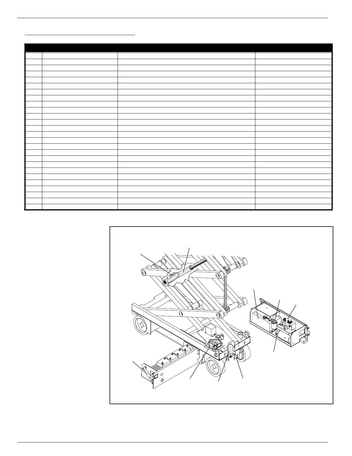
Figure 4-7:
Hydraulic Components Location
Reference
number
Name Function Location
CV Check Valve Allows depression mechanism to retract in drive mode Hydraulic Manifold
CYL1 Steering Cylinder Provides force to turn front wheels Front of Chassis above Drive Motors
CYL2 Lift Cylinder Provides force to lift platform Elevating Assembly
CYL3 Depression Mechanism Cylinder (2) Extends or retracts depression mechanism bar Control Module and Power Module
DVR1 Priority Flow Divider Provides priority fluid flow to steering Hydraulic Manifold
DVR2 Flow Divider Divides fluid to drive motors in parallel drive mode Series/Parallel Manifold
FL1 Suction Strainer (Filter) Traps particles in hydraulic reservoir Inside Hydraulic Reservoir at outlet
FL2 Return Filter Filters fluid returning to reservoir Control Module
MAN Hydraulic Manifold Provides fluid distribution to cylinders, brakes, and series parallel reservoir Control Module
MOT Drive Motors (2) Provides tractive effort to move machine Front Wheels
OR Orifice Restricts fluid return from emergency lowering valve Lift Cylinder
PB Parking Brake (2) Stops machine from moving while parked Internal to Drive Motors
PMP Pump Provides hydraulic pressure for all functions Control Module
RV1 Steering Relief Provides pressure protection to pump and steering components when steering Hydraulic Manifold
RV2 Lift Relief Valve Provides pressure protection to lift system Hydraulic Manifold
RV3 Main Relief Valve Provides pressure protection to hydraulic system Hydraulic Manifold
RES Reservoir Holds hydraulic fluid Control Module
SP Series Parallel Valve Manifold Provides fluid distribution to drive motors Chassis, between Modules
V1 Steering Right/Left Valve Provides directional control for steering Hydraulic Manifold
V2A Lift Valve Provides fluid control for drive or lift functions Hydraulic Manifold
V2B Down/Emergency Lowering Valve Allows fluid to return to reservoir; manually operated for emergency lowering Lift Cylinder
V3A Depression Mechanism Extend Valve Provides fluid control for depression mechanism bar Hydraulic Manifold
V3B Depression Mechanism Retract Valve (2) Provides fluid control for depression mechanism bar Depression Mechanism Cylinders
V4 Forward/Reverse Valve Provides fluid control for drive or lift functions Hydraulic Manifold
V5 Series/Parallel Valve (2) Controls drive speed Series/Parallel Manifold
V6 Counterbalance Valve (2) Provides dynamic braking Hydraulic Manifold
FRONT
V2B
Emergency
Lowering
Valve
SP
Series Parallel
Manifold
CYL3
Depression
Mechanism
Cylinder
CYL1
Steering
Cylinder
CYL2
Lift
Cylinder
MOT
Drive
Motor
PMP
Pump
RES
Hydraulic
Reservoir
FL2
Return
Filter
MAN
Hydraulic
Manifold
Control
Module
Power
Module
 Loading...


