MAIN CIRCUIT Service Manual M4 - M10
29.12.1999 Page 63
L1 L2 L3 DC- DC+L1 L2 L3 DC-
DC+
L1 L2 L3 DC- DC+ L1 L2 L3 DC-
DC+
1.
2.
3. 4.
~0,5V
~0,5V
Infinite
Infinite
Measurements 2 and 4
- diodes biased forward
Measurements 1 and 3
- diodes biased reverse
CX2 and CXL2 up to 55 kW,
CX4 and CXL4 up to 250 kW and
CX5 and CXL5 up to 250 kW:
CX4 and CXL4 , 315 kW... ,
CX5 and CXL5, 315 kW... and
CX6, all power sizes:
Measurements 2 and 4
- diodes biased forward
Measurements 1 and 3
- cannot be done because there
are semicontrolled bridge with
thyristors for charging. See main
circuit diagrams
Figure 8.2 Diode checking from the input terminal
In case, contactor K1 cannot be pulled in manually (Safety warning: do not try
to energise coil of the contactor), checking for the diodes in phases L1 and L3
have to performed by measuring above units from terminals of the charging
contactor K1, instead of input terminals. Notify proper location and order of
the terminals.
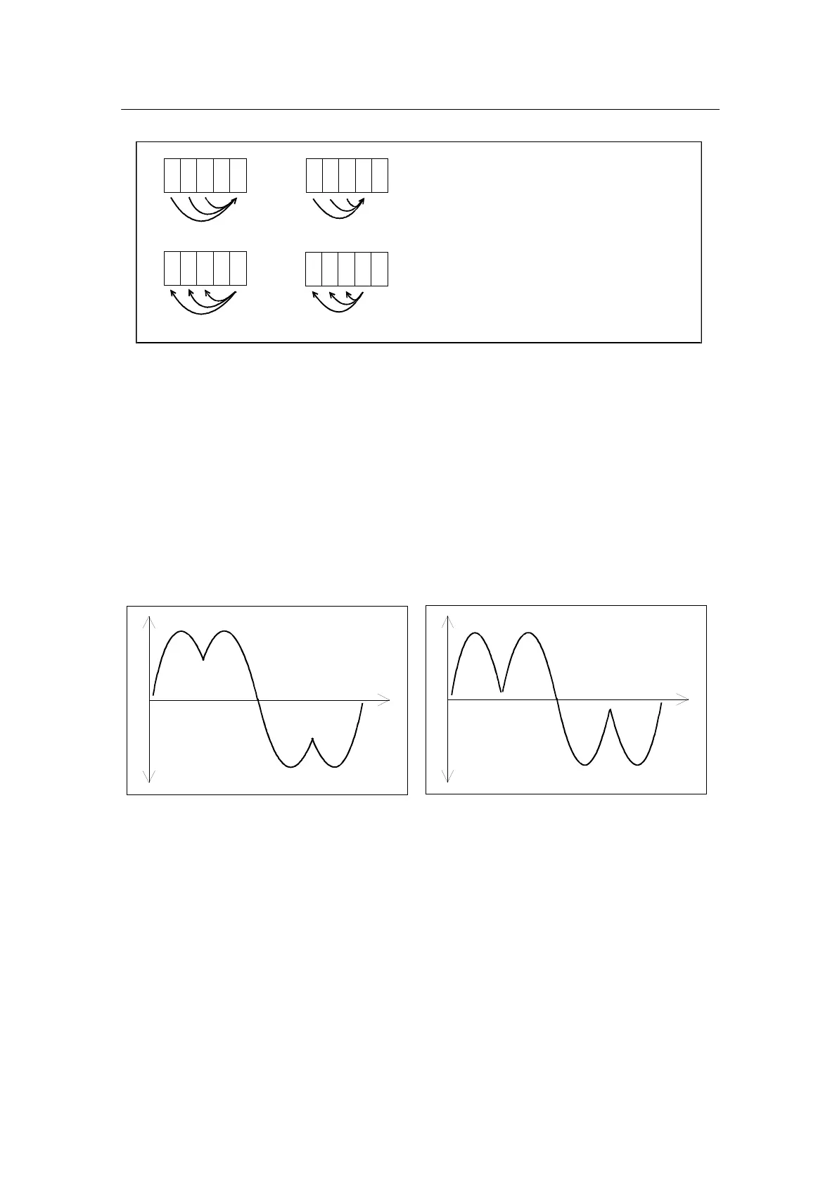
When a drive is powered up by the three phase line and the drive is running
and loaded, the shape of current drawn from the input phase looks as figures
8.3 and 8.4.
Figure 8.3 High inductive reactance Figure 8.4 Lower inductive reactance
On figure 8.3, inductive reactance is higher, than on figure 8.4. Higher
reactance in circuit causes current to drop less on current waveform. Shape
of current waveform is proportional also with rating of the capacitance value
in DC bus and load current drawn from rectifier.
In normal operation phase currents are quite well in balance and each phase
are feeding current into the drive equally. Imbalance in the current compared
from phase to phase is indication of variating impedance between phases
(impedance in line variates some amount and is very normal phenomena).
If voltage is applied to all three phases, but current is not shared equally to all
three phases, loose connection in circuit, or failure (open circuit) in rectifier