PC BOARDS Service Manual M4 - M10
22.10.2001 Page 96
When removing cover from larger units, be careful with the wire used
to make galvanic connection from chassis to the cover “GROUND
WIRE”.
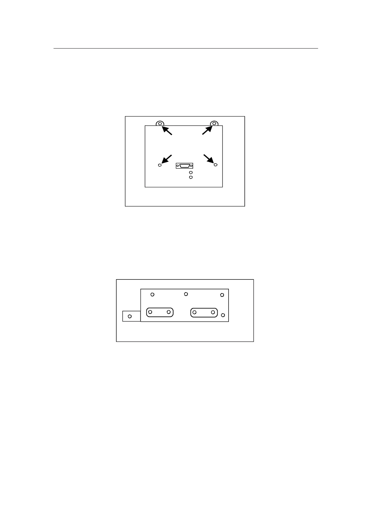
4. To remove the panel holder (bracket), loose and remove four fastening
screws as figure below shows.
Locations of the fastening screws
for panel holder (bracket)
5. When the panel holder is loose, disconnect a ribbon cable from
terminals X1 on the Control board.
In mechanical constructions M4 and M5, particular plate to connect
GND of process cabling is fastened on the Control board and it has to
be removed.
Grounding plate
6. Disconnect all control cables from connectors of the Control boards.
7. Pull out board to board pin connector (2*13 pins) from female socket.
Be very careful to avoid bend pins out of line.
8. Remove a fastening screw to release the Control board. Location of the
screw is pointed out on a layout drawing of the Control board.
On next page is a partial picture of the board to locate the spot of the
screw. The screw provides grounding for the board and in an assembly
phase it has to be tightened properly.