4
vacon • 28 Active Front End (AFE)
Tel. +358 (0) 201 2121 • Fax +358 (0)201 212 205
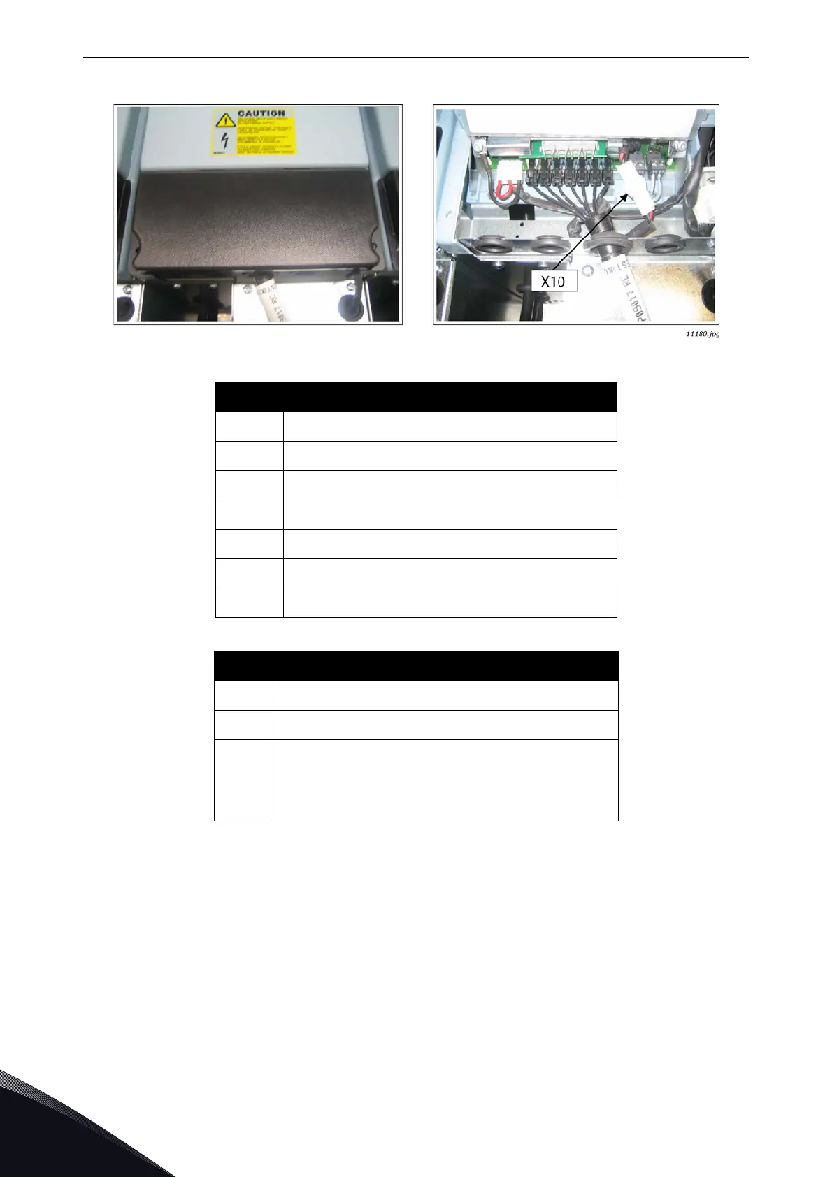
Figure 15. Optical cable terminals in the unit (FI13 example)
NOTE! The minimum fibre cable bending radius is 50 mm.
NOTE! Terminals
X2 and X3 can be in use simultaneously. However, if the +24 V supply from the
control I/O terminals (e.g. from board OPT-A1) is used, this terminal must be protected with a diode.
4.7.2 LCL wiring diagram
The LCL filter contains a choke on the mains side, capacitors and a choke on the AFE side,
Figure 16. The LCL also includes capacitors connected against ground potential. There are
resistors connected across the capacitors for discharging them when the LCL filter is disconnected
from the input power. The discharging resistors are 10 MΩ, 500 V and 0,5 W.
Optical terminals on adapter board
H1
Gate control enable
H2
Phase U control
H3
Phase V control
H4
Phase W control
H5
ADC synchronization
H6
VaconBus data from control board to ASIC
H7
VaconBus data from ASIC to control board
Other terminals on adapter board
X1
Control board connection
X2
Supply voltage 24 V
in
(from power unit ASIC)
X3
Supply voltage 24 V
in
(customer);
•Max. current 1A
• Terminal #1: +
• Terminal #2: –