Installation vacon • 69
24-hour support +358 (0)201 212 575 • Email: vacon@vacon.com
5
When Vacon
®
NX Active Front End is delivered from the factory, the control unit usually includes
two basic boards (I/O board and relay board), which are normally installed in slots A and B. On the
next pages you will find the arrangement of the control I/O and the relay terminals of the two basic
boards, the general wiring diagram and the control signal descriptions. The I/O boards mounted at
the factory are indicated in the type code. For more information on the option boards, see Vacon NX
option board manual (ud741).
The control board can be powered externally (+24 V) by connecting the external power source to
bidirectional terminal #6. This voltage is sufficient for parameter setting and for keeping the
fieldbus active.
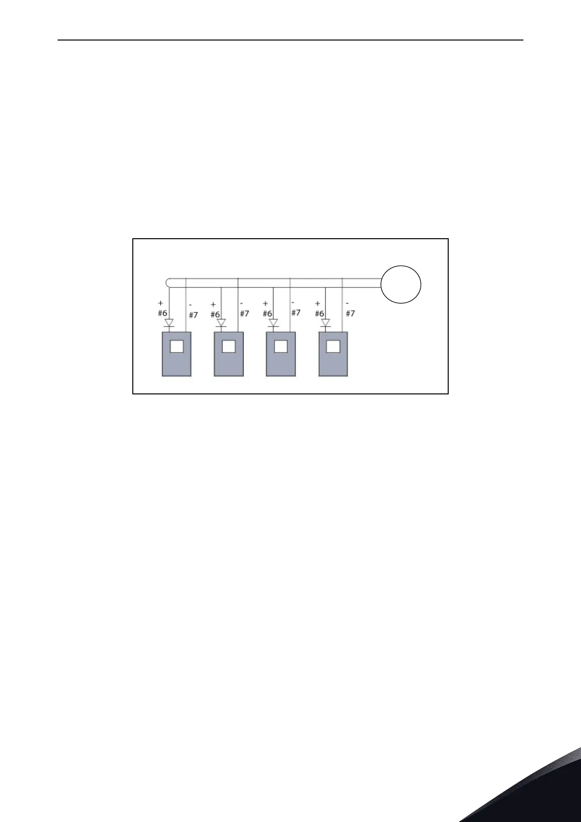
NOTE! If the +24 V input of several brake choppers or other loads are connected in parallel, we
recommend to use a diode in terminal #6 to avoid the current to flow in opposite direction, which
might damage the control board.