8000026412_01 Air/flue pipe installation manual 25
5.9.3 Installing the wall duct
1. Drill a hole.
– Diameter: 125 mm
Note
If the wall duct can be accessed from the
exterior of the building, you can drill the hole
with a diameter of 110 mm and install the
wall duct with the collar from outside.
2. Slide the air/flue pipe (1) with the flexible collar through
the wall.
3. Pull the air/flue pipe back until the collar lies fully on the
external wall.
4. Secure the air/flue pipe with mortar and leave the mor-
tar to harden.
5. Install the collar on the inside of the wall.
6. Connect the wall/roof duct to the product using ex-
tensions, elbows and, if required, a sliding sleeve.
(→ Section 5.19.1)
5.9.4 Connecting the product
Validity: Air/flue pipe, 60/100 mm diameter
1. Install the product (7) – see the installation instruc-
tions for the product.
2. Connect the 87° elbow (1) to the connector for the
air/flue pipe (6).
3. Fit the sliding sleeve (3) with the sleeve as far as it
will go onto the wall duct (4) or the extension (5).
4. If required, install the extensions .
5. Connect the sliding sleeve to the 87° elbow.
6. Install the air pipe clamp (2) for the sliding sleeve.
7.
Alternatives :
Condition: Wall duct with extension
▶ Connect all of the pipe joints with air pipe clamps.
(→ Section 5.19.5)
5.9.5 Variable terminal set (VTK) – 0010039338
5.9.5.1 Minimum clearances for the flue gas terminal
You must comply with the minimum clearances for the flue
gas terminal that are defined in BS 5440, unless the boiler's
manufacturer has given approval to use shorter minimum
clearances that are not considered to be safety-critical.
Vaillant has reduced the minimum clearances for the flue
gas terminal and specifies this in the installation instructions
for the boiler. These are minimum clearances that are to be
used for all types of installation, except for the installation of
the variable terminal set (VTK).
If a variable terminal set is connected to horizontal flue pipe-
work, terminal clearances are reduced for the air inlet. The
terminal clearances on the "new" flue outlet at the end of
VTK remain unchanged.
On the VTK, the minimum clearances for the air inlet A, B
and C (→ Installation instructions for the boiler) to openings
(e.g. a window) are reduced to 150 mm. This means that
the terminal will be at the horizontal flue pipework when a
variable terminal set is connected to the air inlet and can
therefore be installed at a clearance of less than 300 mm
from a window opening or a ventilation tile.
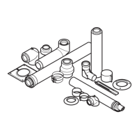
5.9.5.2 Scope of delivery
1 Terminal piece
2 Connection elbow
3 Collar
4 Terminal elbow
5 Bird-guard grille
6 1 m extension (2 pcs)
7 Pipe clamps (3 pcs)
– Variable terminal set, black, article number 0010039338
Note
Components 1, 2 and 3 are not required for the
installation.