Installation
18 Installation and maintenance instructions ecoTEC plus 0020116700_01
4
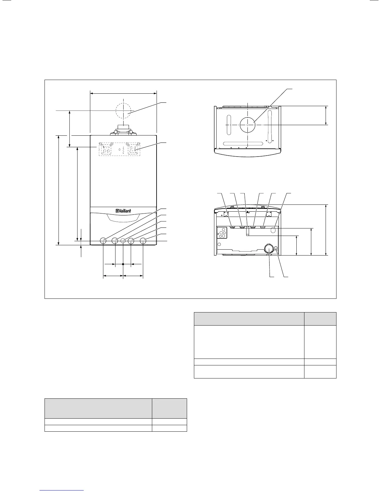
4.5 Dimension drawing and connection
measurements
720
20
35 35
624
B
180
125
125
100100
440
A
2
1
8
3
4
5
6
7
7
9 10
6
3 4 5
11
4.4 Connection measurements inmm
Key
1 Wall breakthrough for air/flue gas duct
2 Hanging bracket
3 Heating flow (22x1.5)
4 Hot water connection (15x1.5), only for VUW boilers
5 Gas connection (15x1.5; ecoTEC 837: 22x1.5)
6 Cold water connection (15x1.5), only for VUW boilers
7 Heating return (22x1.5)
8 Air/flue gas duct connection
9 Condensate siphon
10 Condensate discharge connection, Ø 19mm
11 Heating expansion relief valve discharge pipe connection,
Ø 15mm
Minimum dimension from wall bracket to
center line of air/flue gas duct wall break-
through
Dimension A
[mm]
60/100 with elbow 87°, PP 175
80/125 with elbow 87°, PP 223
4.4 Dimension A for air/flue gas duct wall breakthrough with
VU and VUW boilers
ecoTEC plus installation depth
Dimension B
[mm]
612 (VU GB 126/5-5)
615 (VU GB 156/5-5)
618 (VU GB 186/5-5)
624 (VU GB 246/5-5)
824 (VUW GB 246/5-5)
831 (VUW GB 316/5-5)
335
630 (VU GB 306/5-5) 369
637 (VU GB 376/5-5)
837 (VUW GB 376/5-5)
403
4.5 Dimension B for installation depth on VU and VUW boilers

 Loading...