Electrical installation
34 Installation and maintenance instructions ecoTEC plus 0020116700_01
8
Circulation pump remote control
1
DCF connection
Earth
Earth
External sensor
External temperature sensor
6
Pump PWM signal
Ignition
unit
Bus connection
(Controller/room th. digital)
M
+
X25
7
8
5
3
11
10
+
2
1
9
6
12
X2
8
17
7
18
14
13
4
12
5
7
7
16
4
3
17
24 V
230 V~
X51
5
3
17
4
X22
8
15
13
12
2
X20
X24
X41
X100
2
3
11
6
1
Internal pump *
Ignition
electrode
Auxiliary relay *
(Selection by D.026)
Mains connection
Appliance earth
X16
X18
X1
* ... variant-dependent
230 V AC room thermostat *
No function *
+ 24 V
PWM
Earth
Hall signal
Diverter
valve
Stepper motor
Gas valve
5
1
6
Holding magnet
+
-
1
3
4
red
Flow sensor
blue
Return sensor
Display
Connection
Safety fuse
Coding resistor, output range
Coding resistor, gas group
2
3
4
Burner
off
RT
24
Bus
Water pressure
sensor
Mass flow
sensor
Contact thermostat/burner off
1
2
3
4
5
6
1
2
3
Impeller
sensor
orange
Warm start sensor
Hot water sensor
violet
Fan
12
45
+
-
FB
AF
RF
DCF
0
0
L
N
L
N
N
RT
L
24 V DC room thermostat
blue
pink
white
Edge
connector
white
blue
pink
grey
green
turquoise
white
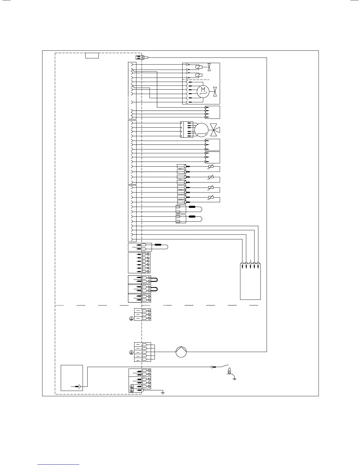
8.5 Connection diagram for electronics box ecoTEC plus 824,
831
 Loading...