Hydraulic installation
24 Installation and maintenance instructions ecoTEC plus 0020116700_01
6
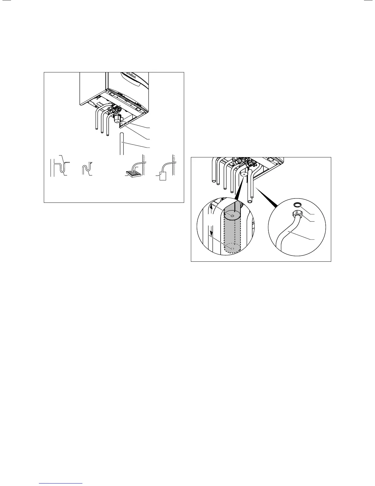
to the discharge pipe. This minimises the risk of the dis-
charge pipe freezing up.
7
d
Soakaway
c
6
5
Gulley
a
Internal
stackpipe
3
4
3
b
Internal
discharge system
11
2
3
6.4 Condensate discharge pipework
> Connect the condensate discharge (1) of the boiler to a
condensate discharge pipework (3) which has a minimum
internal diameter of 19mm (22mm outside diameter for
all external pipes) and is made from an acid-resistant
material (e.g. plastic overflow pipe).
i
The condensate discharge pipework must have a
continuous fall (45mm per metre) and should
whenever possible terminate at a suitable dis-
charge point within the heated envelope of the
building that will remain frost free under long
periods of low external temperatures.
> During installation remove all burs from inside of cut
pipe work and avoid excessive adhesive which may trap
small pockets of water close to the pipe wall which can
freeze and build into a larger ice plug.
> As with other pipe work insulate the condensate dis-
charge pipe to minimise any risk of freezing and beware
when crossing cavities that the fall is maintained and the
pipe sleeved.
> The condensate discharge pipework must terminate in a
suitable location.
Further information can be obtained from "BS 6798 Specifi-
cation for installation of gas–fired boilers of rated input not
exceeding 70 kW net". The condensate siphon (2) must be
filled with water as described in the relevant section before
the boiler is commissioned.
6.7 Connecting the discharge pipe to the
expansion relief valve on the boiler
The expansion relief valve for the heating installation is
integrated in the boiler.
> Install the discharge pipe for the expansion relief valve
so that it does not interfere with the removal and fitting
of the siphon trap.
i
We recommend not to shorten the discharge
pipe supplied.
> Leave an installation space of at least 180mm beneath
the condensate siphon.
min.
180
1
2
3
6.5 Fitting the discharge pipe to the expansion relief valve
(example: VUW boiler)
> Insert a seal (1) in the cap nut (2).
> Screw the discharge pipe (3) onto the expansion relief
valve.
> Make the discharge line routing as short as possible and
sloping away from the boiler.
> Allow the line to terminate in such a way that nobody
can be injured and no cable or other electrical compo-
nents can be damaged if water or steam is ejected.
> Please note that the end of the line must be visible.

 Loading...