Inspection and maintenance
Installation and maintenance instructions ecoTEC plus 0020116700_01 63
12
> Close the gas isolator cock on the boiler.
> Close the service valves on the boiler.
> Remove the front casing from the boiler
(¬section4.7).
> Fold the electronics box forwards (¬section8.2).
1
2
4
3
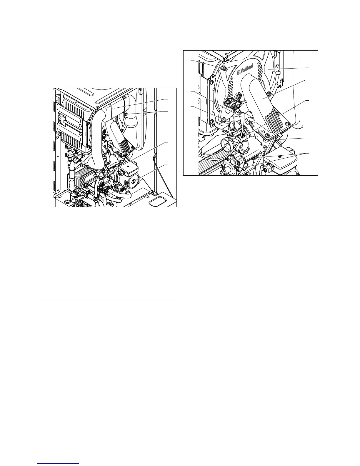
12.3 Remove the air intake pipe
> Unscrew the retaining screw (2, ¬fig.12.3) and detach
the air intake pipe (1, ¬fig.12.3) from the intake stub.
b
Caution.
Risk of damage to the gas pipe.
The corrugated gas pipe may become dam-
aged.
> Do not suspend the compact thermal
module on the flexible corrugated gas
pipe.
> Do not suspend any loads from the cor-
rugated gas pipe.
> Either unscrew the cap nut (3,
¬fig.12.3) from the gas valve or the cap nut (4,
¬fig.12.3) between the corrugated gas pipe and the
fixed gas pipe.
1
2
4
3
5
8
7
6
12.4 Removing the compact thermal module
i
The plugs at the fan motor and the venturi have
latching lugs with which they engage in the slot.
You have to push in the latching lug to pull off
the plug.
> Remove the plug of the ignition line (7, ¬fig.12.4) and
the ground connection (6, ¬fig.12.4) from the ignition
electrode.
> Remove the plug (4, ¬fig.12.4) from the fan motor.
> Remove the three plugs from the gas valve (5,
¬fig.12.4).
> Remove the plug from the venturi (3, ¬fig.12.4).
> Release the cable harness from the clip on the gas valve
retainer.
> Unscrew the four nuts (8, ¬fig.12.4).
> Remove the entire compact thermal module (2,
¬fig.12.4) from the heat exchanger (1, ¬fig.12.4).
> Once removed, check the burner and the heat exchanger
for damage and dirt.
> If necessary, clean the components according to the fol-
lowing sections.
> Check the burner flange insulation on the module. If
signs of damage, other than small cracks, are apparent
you must replaced it (article number193 595).
 Loading...