Troubleshooting
70 Installation and maintenance instructions ecoTEC plus 0020116700_01
13
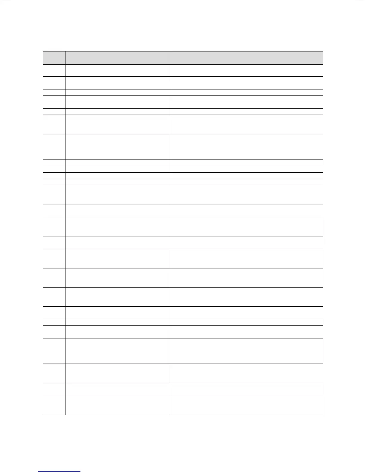
Code Meaning Cause
F.49 eBUS fault Short circuit on eBUS, eBUS overload or two power supplies with different
polarities on the eBUS
F.52 Mass flow sensor connection fault Mass flow sensor not connected/disconnected, plug not connected or
incorrectly connected
F.53 Mass flow sensor fault Mass flow sensor faulty, filter below venturi filter cap wet or blocked
F.54 Gas pressure fault (in combination with F.28/F.29) No or too little gas supply pressure, gas valve closed
F.56 Fault: Mass flow sensor regulation Gas valve defective, cable harness to gas valve defective
F.57 Fault during comfort safety mode Ignition electrode highly corroded
F.61 Fault: Gas valve regulation - Short circuit/short to earth in cable harness for the gas valve
- Gas valve defective (coils shorted to earth)
- Electronics defective
F.62 Fault: Gas valve switch-off delay - Delayed shutdown of gas valve
- Delayed extinguishing of flame signal
- Gas valve leaking
- Electronics defective
F.63 EEPROM error Electronics defective
F.64 Electronics/NTC fault Supply or return NTC short circuited, electronics defective
F.65 Electronic temperature fault Electronics overheating due to external influences, electronics defective
F.67 Electronics/flame fault Implausible flame signal, electronics defective
F.68 Unstable flame signal fault Air in gas, gas flow pressure too low, wrong air ratio, condensate route
blocked, wrong gas restrictor, ionisation flow interruption (cables, elec-
trodes), flue gas recirculation, condensate route
F.70 Invalid device specific number (DSN) Spare part case: Display and PCB replaced at same time and DSN not set,
wrong or missing output range coding resistance
F.71 Flow NTC fault Flow temperature sensor signalling constant value:
- Flow temperature sensor incorrectly positioned at supply pipe.
- Flow temperature sensor defective.
F.72 Flow/return NTC fault Flow/return NTC temperature difference too great -> flow and/or return
temperature sensor defective
F.73 Water pressure sensor signal in the wrong range
(too low)
Interruption/short circuit of water pressure sensor, interruption/short cir-
cuit to GND in supply line to water pressure sensor or water pressure sen-
sor defective
F.74 Water pressure sensor signal outside correct
range
(too high)
Cable to water pressure sensor has short-circuited at 5 V/24 V
or internal fault in water pressure sensor
F.75 Fault, no pressure change detection when start-
ing pump
Water pressure sensor and/or pump defective, air in heating installation,
too low water pressure in boiler; check adjustable bypass, connect external
expansion vessel to return
F.76 Overheating protection on primary heat
exchanger has responded
Cable or cable connections for safety fuse in primary heat exchanger or
primary heat exchanger defective
F.77 Flue non-return flap/condensate pump fault No response from flue non-return flap or condensate pump defective
F.78 Interruption to DHW outlet sensor at external
controller
UK link box is connected, but hot water NTC not bridged
F.83 Flow and/or return temperature sensor tempera-
ture change fault
When the burner starts, the temperature change registered at flow and/or
return temperature sensor is non-existent or too small.
- Not enough water in the boiler
- Flow and/return temperature sensor not in correct position at pipe.
F.84 Fault: Flow/return temperature sensor tempera-
ture difference implausible
Flow and return temperature sensors returning implausible values.
- Flow and return temperature sensors have been inverted.
- Flow and return temperature sensors have not been correctly fitted.
F.85 Fault: Flow and return temperature sensors incor-
rectly fitted
Flow and/or return temperature sensors
have been fitted to the same pipe/wrong pipe.
F.92 Coding resistance fault The coding resistance on the PCB does not match the entered gas family
Check the resistance, repeat the gas family check and enter the correct
gas family.
13.2 Fault codes (continued)
 Loading...