Chapter 2 ___________________________________________________________ Product Overview
VAISALA ________________________________________________________________________ 15
Transmitter Parts
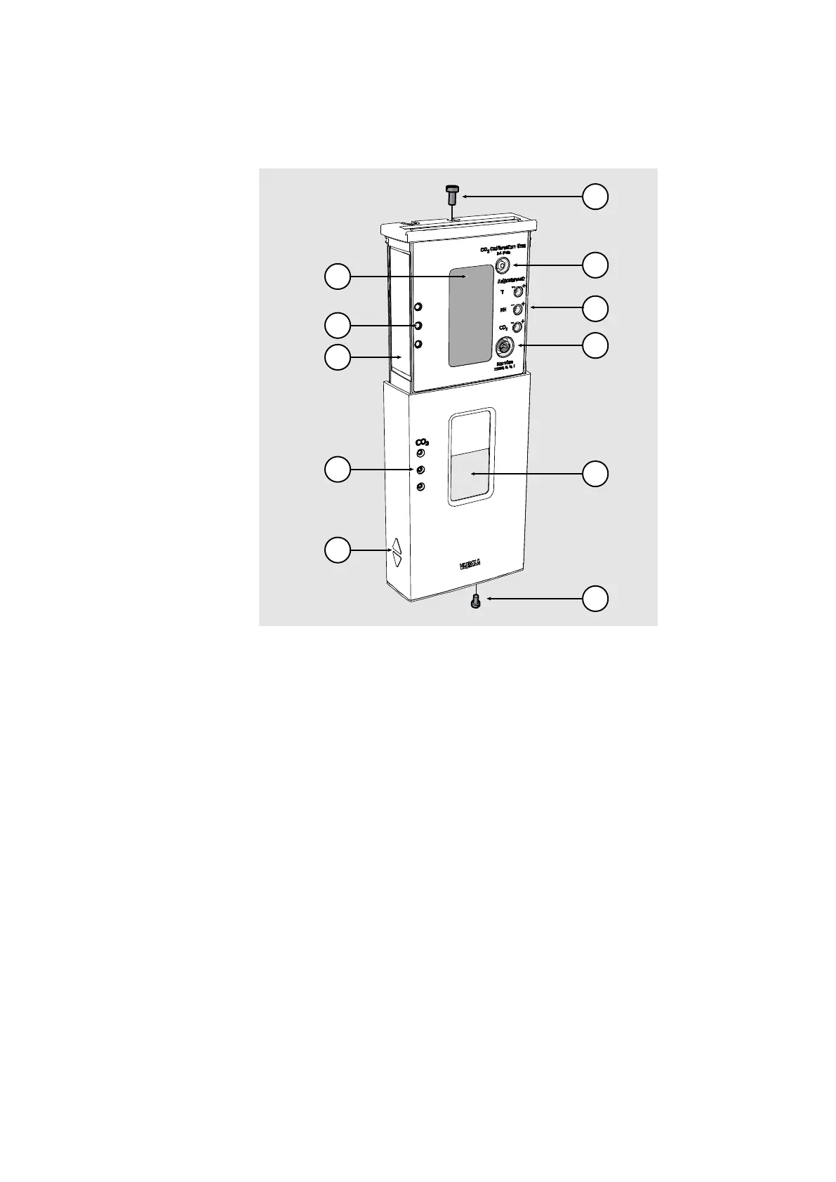
1310-038
Figure 2 Transmitter Parts - Outside
Locking screw for mounting base (M3×6).
2
calibration gas.
Use a 3 mm inner diameter silicone tube and 0.4 l/min flow.
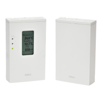
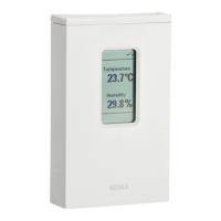
Window for display (only in models where the display is visible)
Locking screw for slide (M3×6).
2
level indicator LEDs. Enabled on models with LED option.
Default settings:
- Green LED (bottom): lit between 0 ... 800 ppm CO
2
.
- Yellow LED (middle): lit between 800 ... 1200 ppm CO
2
.
- Red LED (top): lit between 1200 ... 5000 ppm CO
2
,
blinking at > 5000 ppm CO
2
.
Holes for indicator LEDs (only in models with LED option).
 Loading...