39
Install Electrical Wiring (for optional
accessories)
This section provides information to install the electric
pre-wiring required for use with the 1595CFK Circulat-
ing Fan Kit and/or the 1565LLK Lighting Kit.
All wiring must be done by a qualifi ed electrician in
accordance with local codes or, in the absence of
local codes, with the National Electrical Code, ANSI/
NFPA 70 or the Canadian Electrical Code, CSA C22.1.
Electrical Requirements
1595CFK—120 V, 60 Hz, less than 1 amp
1565LLK—120 V, 60 Hz, 200 W, halogen
General Requirements
Both optional 1595CFK and 1565LLK kits include a
three-prong grounded plug to plug into a grounded du-
plex receptacle installed within the fi replace enclosure
by a qualifi ed electrician.
Notes
• A fan speed control and/or lighting dimmer switch
will need to be provided by the electrician, mounted
at a convenient location on the wall, and connected
to control power supply to each of the receptacles
within the fi replace enclosure.
• If using both accessories, separate cables or switch
legs will be required and the duplex receptacle will
need to be “split” to ensure separate control of fan
and lighting.
• The duplex receptacle and box must be located as
per these instructions. Wiring within this box must
have a minimum 90°C temperature rating.
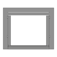
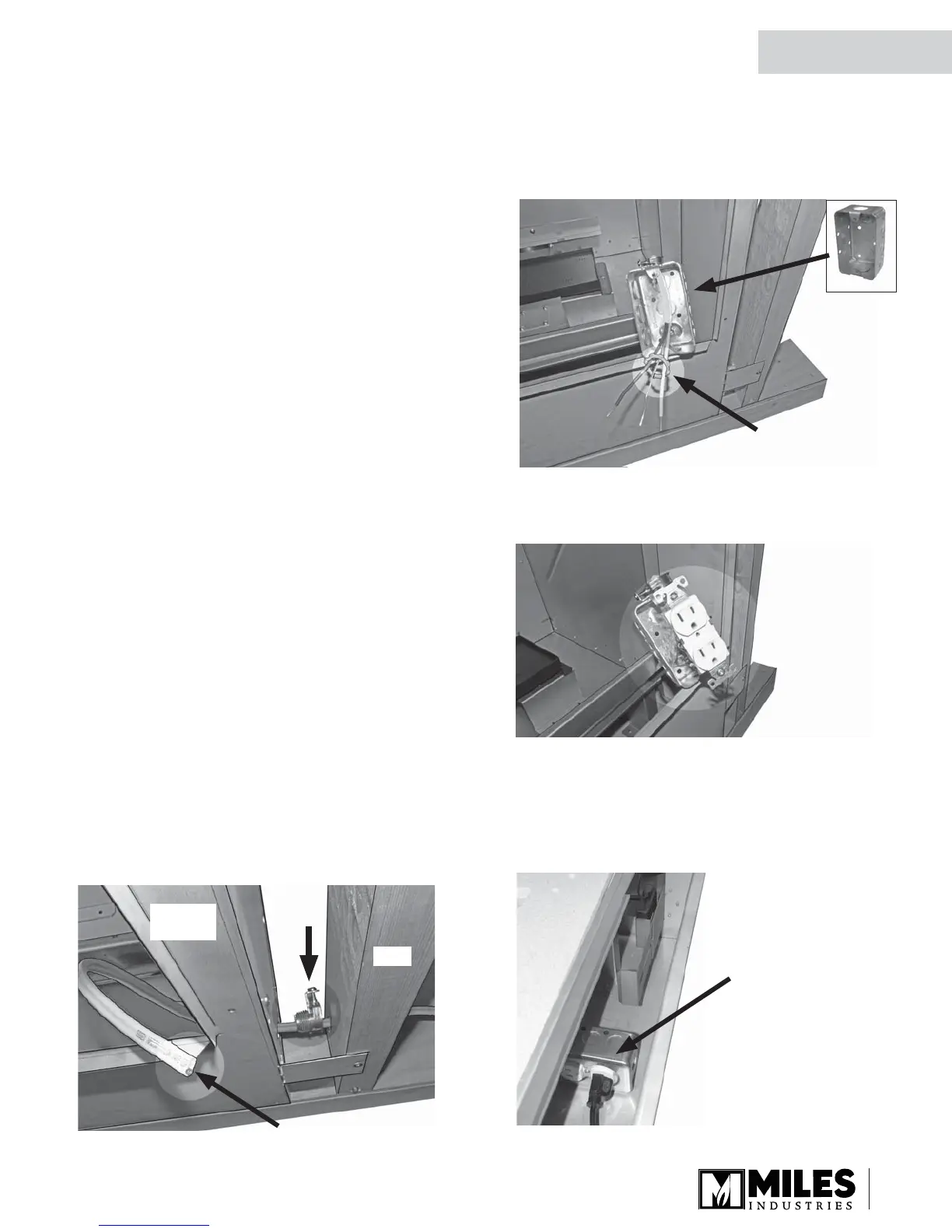
Installation
1. Thread the cable through the cable clamps and
through the hole in the lower right hand corner of
the fi replace casing. Do not tighten the clamps yet.
Note: May require a 3-wire cable and ground for
independent control of fan and lighting.
Cable clamp
locking ring
2. Provide a steel surface mount electrical utility box
(Iberville BC 1110 or equivalent), thread cable
through knock-out in the end of box and through the
cable clamp locking ring (if used).
3. Strip wire and terminate grounded receptacle. “Split”
receptacle and control separately if using fan and
lighting control.
4. Mount receptacle into electrical box.
5. Mount steel cover to electrical box and plug in the
accessory cable(s).
6. Position the electrical box to the base of the
fi replace with accessory cables plugged in
sideways, layed sideways.
Stud
Fireplace
casing
Pull just enough cable
out front for now to
make termination easier
Positioned
sideways inside
fi rebox
Installation
QUALIFIED
INSTALLER
 Loading...