2.23 Inverse time operation 2 Protection functions Technical description
100
VAMP 24h support phone +358 (0)20 753 3264 VM50.EN004
Limitations
The minimum definite time delay start latest, when the
measured value is twenty times the setting. However, there are
limitations at high setting values due to the measurement
range. See chapter 2.23 for more details.
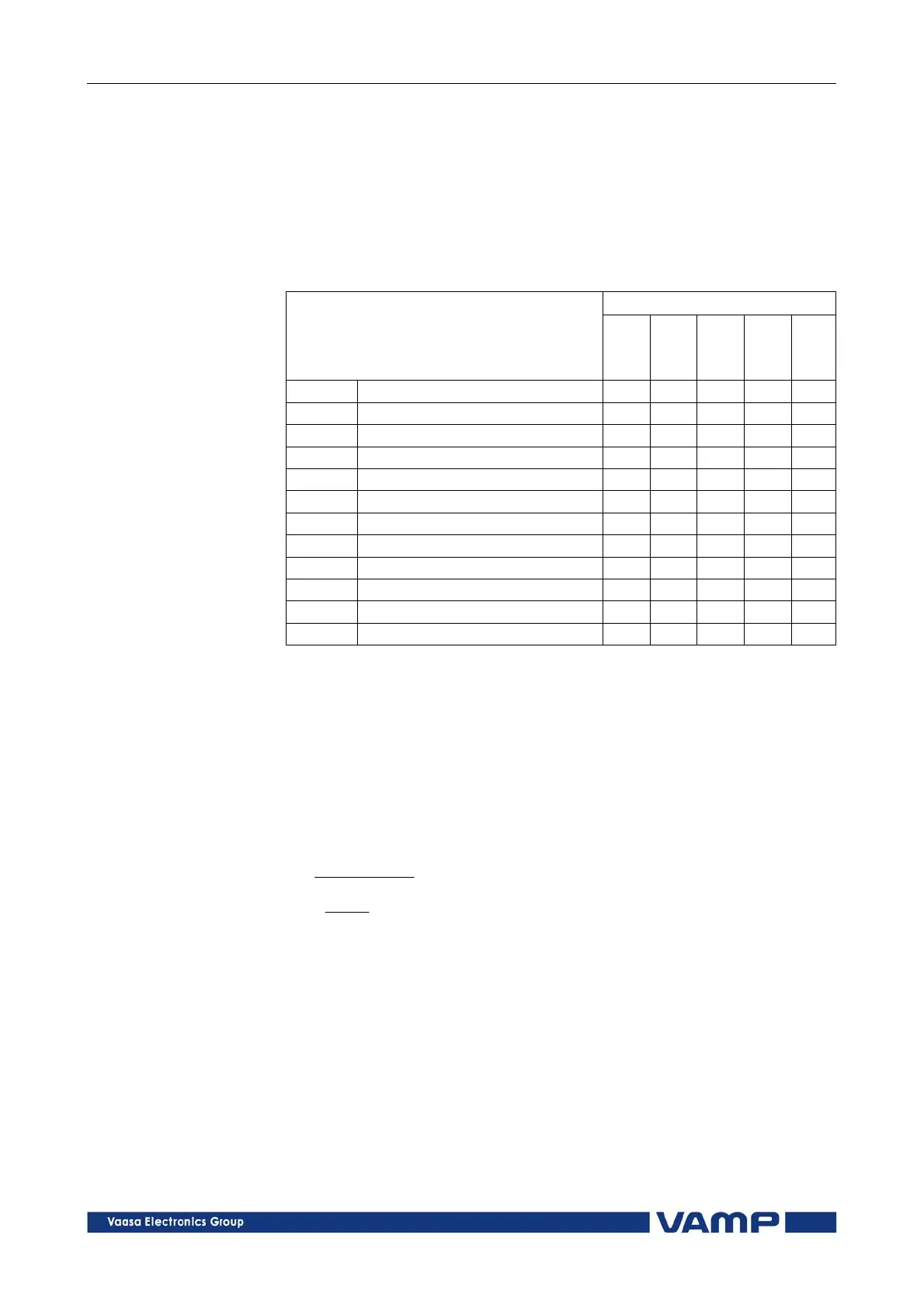
Table 2.23.1-1. Available standard delay families and the
available delay types within each family.
Curve family
Delay type
DT
IEC
IEEE
IEEE2
RI
DT Definite time X
NI1 Normal inverse X X
VI Very inverse X X X
EI Extremely inverse X X X
LTI Long time inverse X X
LTEI Long time extremely inverse X
LTVI Long time very inverse X
MI Moderately inverse X X
STI Short time inverse X
STEI Short time extremely inverse X
RI Old ASEA type X
RXIDG Old ASEA type X
IEC inverse time operation
The operation time depends on the measured value and other
parameters according Equation 2.23.1-1. Actually this equation
can only be used to draw graphs or when the measured value I
is constant during the fault. A modified version is implemented
in the relay for real time usage.
Equation 2.23.1-1
1
B
pickup
I
I
Ak
t
t = Operation delay in seconds
k = User’s multiplier
I = Measured value
Ipickup = User’s pick up setting
A, B = Constants parameters according Table 2.23.1-2.
There are three different delay types according IEC 60255-3,
Normal inverse (NI), Extremely inverse (EI), Very inverse (VI)