4.11 Primary, secondary and per unit
scaling
4 Measurement functions Technical description
146
VAMP 24h support phone +358 (0)20 753 3264 VM50.EN004
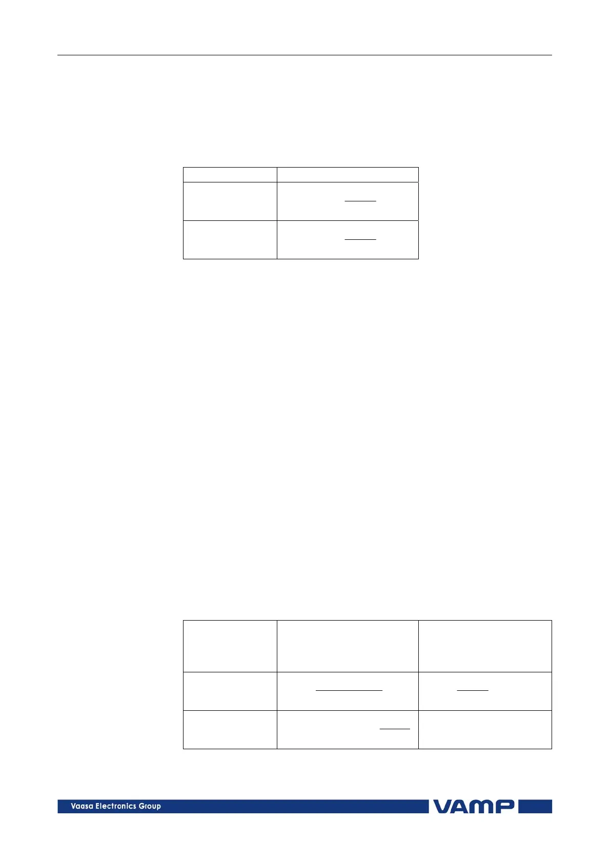
4.11.1. Current scaling
NOTE! The rated value of the relay's current input 5 A, does not have any effect
in the scaling equations, but it defines the measurement range and the
maximum allowed continuous current. See chapter 9.1.1 for details.
Primary and secondary scaling
Current scaling
secondary primary
SEC
PRI
SECPRI
CT
CT
II
primary secondary
PRI
SEC
PRISEC
CT
CT
II
For residual current to input I
01
use the corresponding CT
PRI
and CT
SEC
values. For earth fault stages using I
0Calc
signals use
the phase current CT values for CT
PRI
and CT
SEC
.
Example 1: Secondary to primary.
CT = 500/5
Current to the relay's input is 4 A.
Primary current is I
PRI
= 4x500/5 = 400 A
Example 2: Primary to secondary.
CT = 500/5
The relay displays I
PRI
= 400 A
Injected current is I
SEC
= 400x5/500 = 4 A
Per unit [pu] scaling
For phase currents excluding ArcI> stage
1 pu = 1xI
mode
= 100 %, where
I
mode
is the rated current of the motor or the nominal value of
the feeder.
For residual currents and ArcI> stage
1 pu = 1xCT
SEC
for secondary side and
1 pu = 1xCT
PRI
for primary side.
Phase current scaling
excluding ArcI> stage
Residual current (3I
0
)
scaling and phase
current scaling for ArcI>
stage
secondary per unit
MODESEC
PRISEC
PU
ICT
CTI
I
SEC
SEC
PU
CT
I
I
per unit secondary
PRI
MODE
SECPUSEC
CT
I
CTII
SECPUSEC
CTII