Operation and configuration 2 Local panel user interface 2.1 Relay front panel
2. Local panel user interface
2.1. Relay front panel
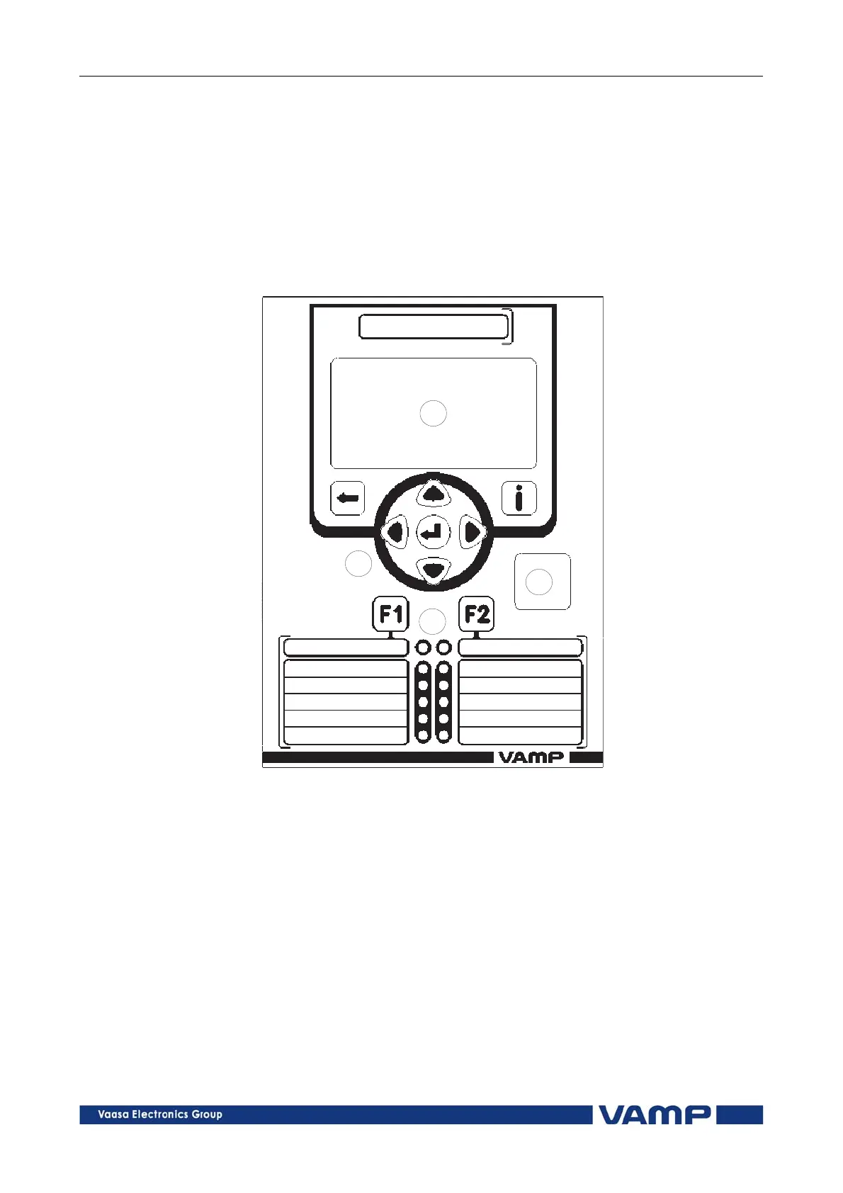
The figure below shows, as an example, the front panel of the
overcurrent and earthfault protection relay VAMP 50 and the
location of the user interface elements used for local control.
VAMP50Front
1
2
3
4
Figure 2.1-1. Relay front panel
1. LCD dot matrix display
2. Keypad
3. LED indicators
4. USB communication port for PC
VM50.EN004 VAMP 24h support phone +358 (0)20 753 3264
5