2.5 Overcurrent protection I>
(50/51)
VAMP 24h support phone +358 (0)20 753 3264
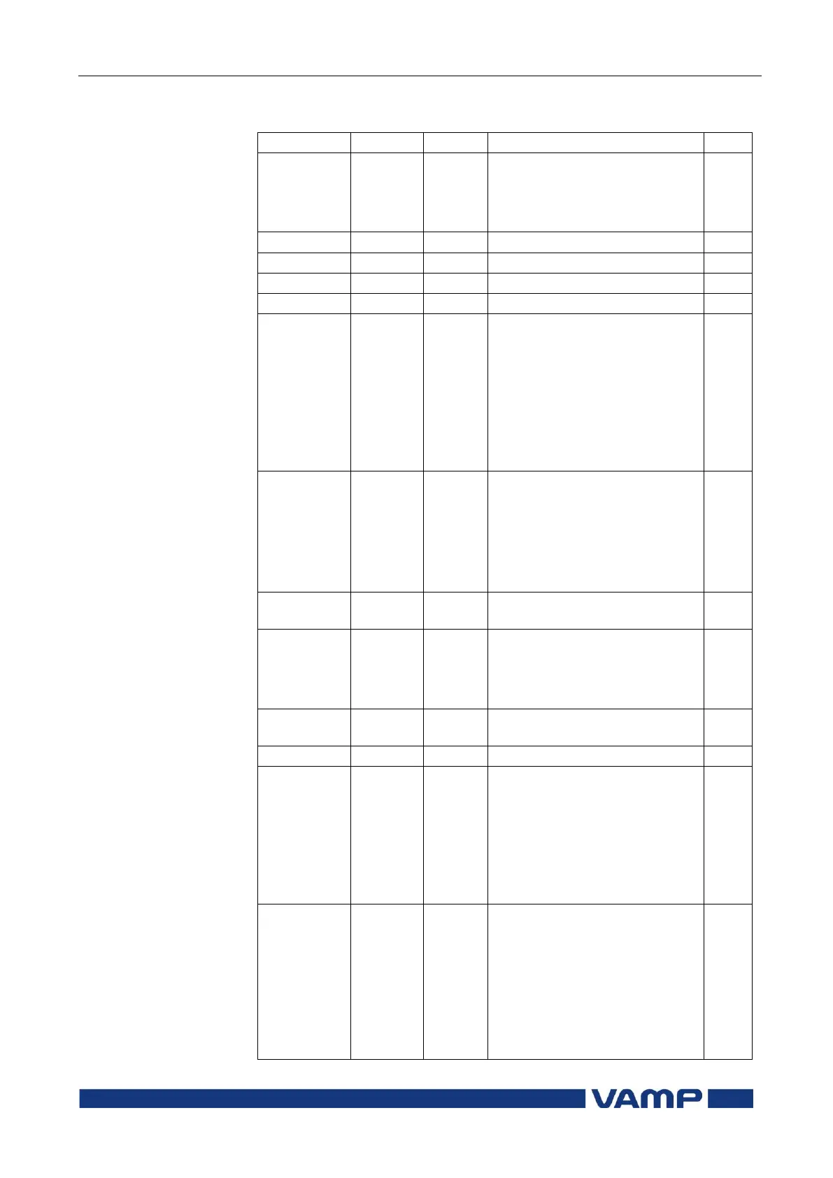
Parameters of the overcurrent stage I> (50/51)
Current status of the stage
Digital signal to select the
active setting group
None
Digital input
Virtual input
LED indicator signal
Virtual output
Function key
Force flag for status forcing for
test purposes. This is a
common flag for all stages and
output relays, too. This flag is
automatically reset 5 minutes
after the last front panel push
button pressing.
The supervised value. Max. of
IL1, IL2 and IL3
Pick-up value scaled to
primary value
DT
IEC
IEEE
IEEE2
RI
PrgN
Delay curve family:
Definite time
Inverse time. See chapter 2.14.
Pre 1996
DT
NI
VI
EI
LTI
Para-
meters
Delay type.
Definite time
Inverse time. See chapter 2.14.