2.12 Line differential protection
LdI> (87L)
VAMP 24h support phone +358 (0)20 753 3264
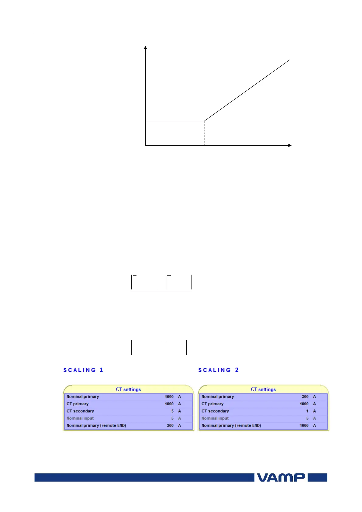
dI> pick-up
Basic setting
Start of slope (Basic limit)
Figure 2.12-1 Tripping threshold characteristics
Bias current calculation is only used in protection stage I>.
Bias current describes the average current flow in transformer.
Bias and differential currents are calculated individually for
each phase.
Equation 2.12-1: Bias current
Equation 2.12-2: Differential current
Figure 2.12-2 Example settings