Run 9
________________________________________________________________________________________
_______________________________________
9-50
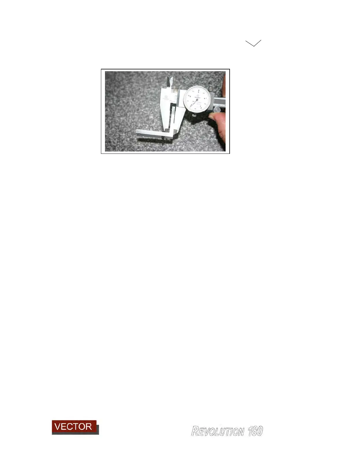
It is also a simple matter to measure the setting using callipers as in the image below.
Adjustment can be made to the set screws and a measurement taken to check the
change in setting.
Now release the two locking screws (981) on top of the horizontal shoe, replace the
adjuster block (with it’s new set screw settings) and push the horizontal shoe back against
the two screws and sideways against the single lateral screw.
Lock down the screws (981) again. This will have set the new position for the shoe.
Adjusting the shoe in and out will increase or reduce the radius shape.
Adjusting the shoe sideways will not affect the shape of the radius except on a corner.
The reason for this is that as the shoe travels around tight corners, the contact point of the
shoe against the panel changes slightly. For example on a small radius external corner,
the contact point of the shoe rolls around closer toward the front (87) of the shoe.
Thus moving the shoe in this direction will reduce the radius shape on the external corner.
Conversely moving the shoe away in the opposite direction (toward the scraper unit) will
increase the radius.
Trial and error will find the correct position to maintain an even radius around corners
which matches the radius along straight or sweeping edges.
When you are satisfied with the shape of the radius, it is time to set the vertical tracer
shoes which controls how close the trimmers cut on the top and bottom surfaces of the
panel.
9.2.7.2 Setting the vertical tracer shoes.
The vertical position of the trimmers in relation to the panel are controlled by one top
vertical tracer shoe (929) and a lower vertical tracer shoe (930).