Setup Mode Setup Mode Categories
19
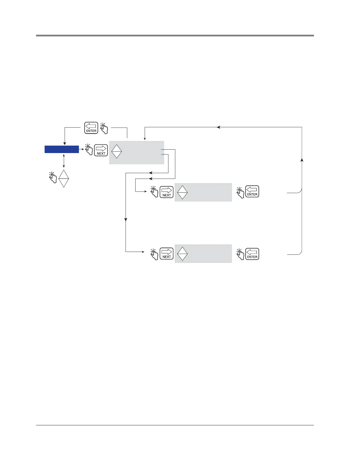
RELAY CONTROL
The EMR4 must be in Preset Mode to control the flow valve solenoid(s). For a single-stage flow valve, use Relay 2
(Stop), for a dual-stage flow valve, use Relay 1 (Slow) and Relay 2 (Stop).
NOTE: Pushing the FINISH button at any time will cause a manual override condition and both relays will open.
When the relays open, both solenoids close, halting fuel flow.
Figure 15 illustrates Relay Control setup in Setup Mode.
Figure 15. Relay Control Setup
NOTE:
See EMR4 Installation Guide, 577013-758 for Relay 1 (Slow) and Relay 2 (Stop) wiring connections to flow valve
Solenoid 1 (Fast Flow) and Solenoid 2 (Stop).
RELAY CONTROL
-
+
+
-
+
+
-
+
RELAY 1 SLOW XXX
RELAY 2 STOP XXX
SET ADVANCE 1 XXX
+
-
+
SET ADVANCE 2 XXX
Note: This entry sets the number of volume
units prior to the finish of a preset delivery,
at which point, Relay 1 (Slow) will open,
causing the fast flow solenoid of a dual-stage
flow valve to close, halting flow. Recommended
setting is 5 volume units.
Note: Flow control relays are located
in the IB box. Each Display Head (1 or 2)
has two relays assigned to it. Installations
with only a
single-stage flow valve use
RELAY 2 (Stop).
Note: This entry sets the number of volume
units prior to the finish of a preset delivery,
at which point, Relay 2 (Stop) will open,
causing the single-stage flow valve solenoid
to close, or the stop solenoid of a dual-stage
flow valve to close, halting flow.
Recommended setting is 0.1 volume units.
Press ENTER
to accept
selection and
return to
Press ENTER
to accept
selection and
return to
SECURITY
PRINTER OPTION
VIEW RECORDS
RESTORE RECORD
SHIFT
DATE FORMAT
TIME/DATE
SYSTEM ADDRESS
TIME DELAYS
VERSION NUMBER
C AND C
ENTER SECURITY CODE
PRICING
TAX/DISCOUNT
DEFAULTS
Press the up/down
buttons to cycle
through remaining
Setup Mode categories