63
EMR4 Troubleshooting Guide
Most errors are the result of poor terminations of wiring, either in a junction box, or at the terminal strips in the IB
box or Display Head.
Note: The EMR4 encoder is a 2-channel quadrature pulse output device in which the A-channel leads the B-
channel by 90 degrees in order to create 4 unique states.
Available Documentation
For EMR4 hardware related details, see the EMR4 Application Guide, number 577014-339. For information
related to menus or settings, see the EMR4 Setup and Operation Manual, number 577014-350. Descriptions of
the EMR4 System are available on the UL/cUL Control Drawing, document number 331940-021 or the ATEX
System Drawing, document number 331940-022. Veeder-Root documents are available on our web site at: http://
www.veeder.com/us/products/meter-registers/electronic-meter-registers/electronic-meter-register-EMR4.
Testing an EMR4System
DISPLAY HEAD
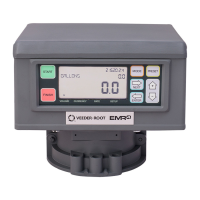
To perform a Display Head Complete Self-Diagnostic Check, cycle power to the EMR4 system. To cycle power,
turn the power off for at least 20 seconds before turning it on again. During power up, each Display Head
automatically tests all its own circuit board hardware in about 30 seconds. If a failure occurs, an error code
number described in this guide, is posted on the display.
LCD DISPLAY
To test the LCD Display, simulate a delivery by performing a START and FINISH sequence in Volume or Currency
mode. The fueling nozzle icon will appear after pressing the START button. For a brief period of time, all of the
segments will turn on, then off. If the unit fails to perform this test, press the FINISH button once, then press
START and FINISH again. The nozzle icon should appear after START and disappear after FINISH, if not then the
head will need to be replaced.
PULSE GENERATOR INPUT CHECK
With the cover open and the unit NOT in C&C mode, disconnect the spring between the pulse generator and the
input shaft. Push start and turn the pulse generator shaft until a nonzero reading appears on the register portion of
the display. Press the FINISH button, the nozzle icon turns off and a delivery ticket is printed. BE SURE TO
RECONNECT THE SPRING BEFORE REPLACING THE LID.
PRINTER CHECK
Verify ticket printing by either printing duplicate tickets or by simulating a delivery as noted above. Push the FINISH
button to display a previous delivery on the register display. To print a duplicate ticket, hold the FINISH button
down for a few seconds then release it.
EMR4 Informational Messages
All messages appear in the Display Head’s 14-character Descriptor Field (ref. Figure 1 on page 4). System
messages can be either informational or describe an error detected by the self-checking functions of the EMR4.
Information messages do not inhibit the operation of the EMR4.

 Loading...