24
4 Mounting
VEGAPULS 69 • Foundation Fieldbus
47251-EN-160815
Distance d
(m)
2° 4° 6° 8° 10°
80 2.8 5.6 8.4 11.1 13.9
90 3.1 6.3 9.4 12.5 15.6
100 3.5 7 10.5 13.9 17.4
110 3.8 7.7 11.5 15.3 19.1
120 4.2 8.4 12.5 16.7 20.8
Example:
In a vessel 20 m high, the installation position of the sensor is 1.4 m
from the vessel centre.
The necessary angle of inclination of 4° can be read out from this
table.
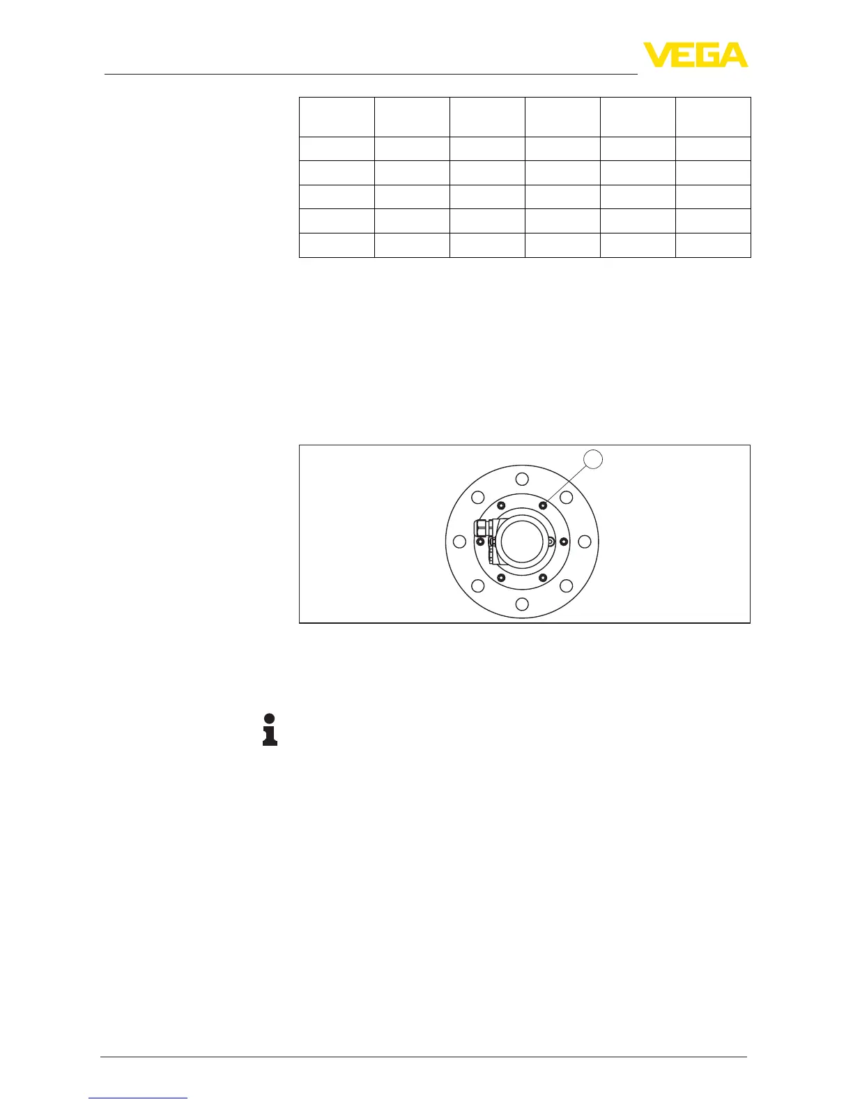
Proceed as follows to adjust the angle of inclination with the swivelling
holder:
1. Loosen the terminal screws of the swivel holder by one turn. Use
ahexagonsocketwrench,size5.
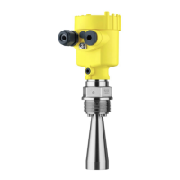
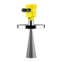
Fig.16:VEGAPULS69withswivellingholder
1 Terminalscrews(6pcs.)
2. Align the sensor, check angle of inclination
Information:
The max. angle of inclination of the swivelling holder is approx. 10°
3. Re-tighten the terminal screws, max. torque see chapter "Techni-
cal data".
The mounting location of the radar sensor should be a place where no
otherequipmentorxturescrossthepathoftheradarsignals.
Vessel installations, such as e.g. ladders, limit switches, heating spi-
rals, struts, etc., can cause false echoes and impair the useful echo.
Make sure when planning your measuring point that the radar sensor
has a "clear view" to the measured product.
In case of existing vessel installations, a false signal suppression
should be carried out during setup.
If large vessel installations such as struts or supports cause false
echoes, these can be attenuated through supplementary measures.
Small,inclinedsheetmetalbaesabovetheinstallationsscatterthe
radarsignalsandpreventdirectinterferingreections.
Vessel installations


 To Next Page