37
6 Set up with the display and adjustment module
VEGAPULS 69 • Foundation Fieldbus
47251-EN-160815
1 2
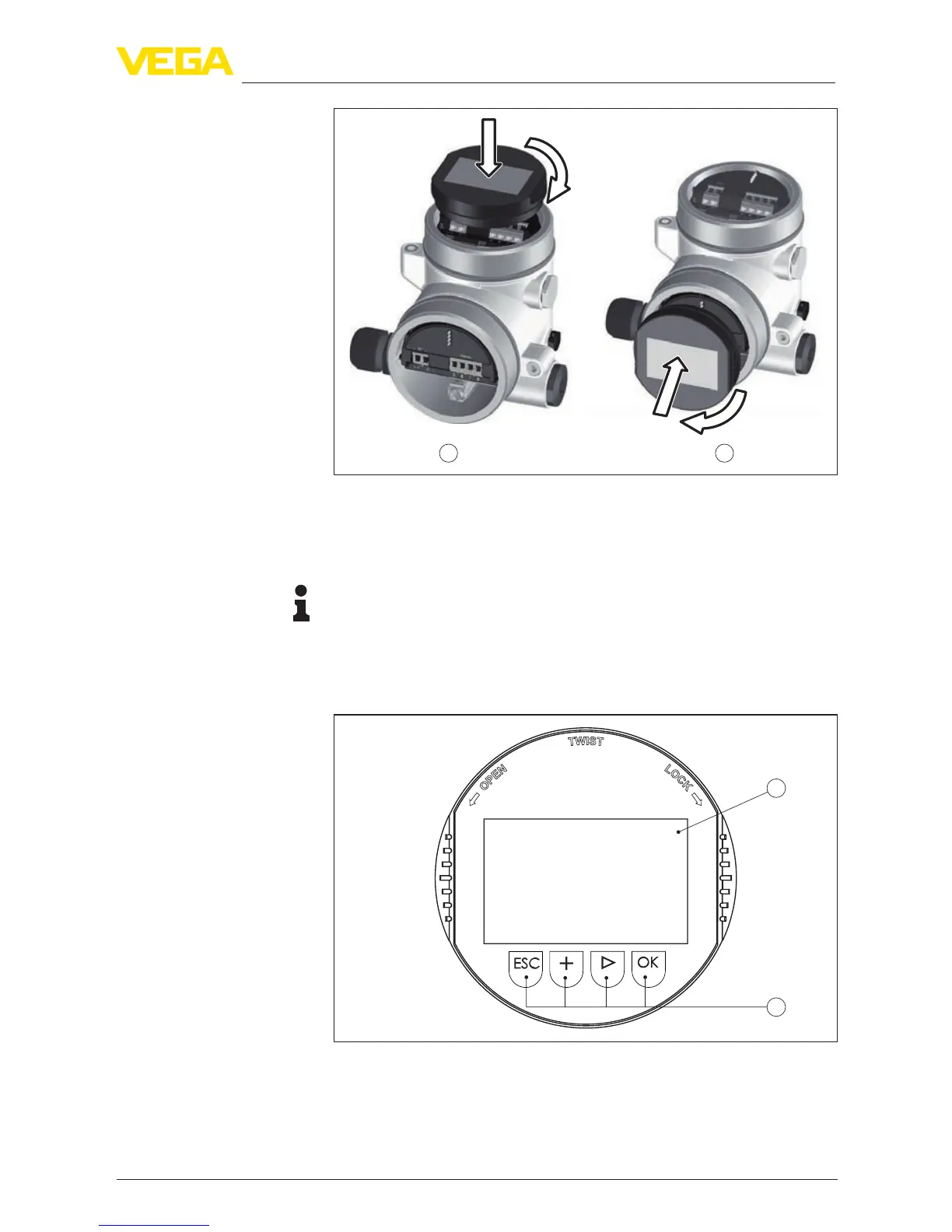
Fig. 34: Installing the display and adjustment module in the double chamber
housing
1 In the electronics compartment
2 In the terminal compartment
Note:
Ifyouintendtoretrottheinstrumentwithadisplayandadjustment
module for continuous measured value indication, a higher lid with an
inspection glass is required.
6.2 Adjustment system
1
2
Fig. 35: Display and adjustment elements
1 LCdisplay
2 Adjustment keys
•
[OK] key:Key functions