34
5 Connecting to the bus system
VEGAPULS 69 • Foundation Fieldbus
47251-EN-160815
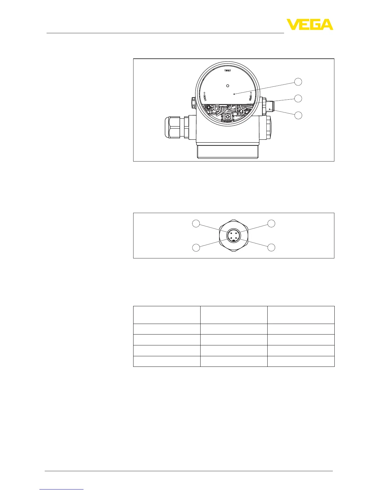
5.5 Double chamber housing with DISADAPT
3
1
2
Fig.31:ViewtotheelectronicscompartmentwithDISADAPTforconnectionof
the external display and adjustment unit
1 DISADAPT
2 Internal plug connection
3 Plug connector M12 x 1
34
1
2
Fig. 32: View to the plug connector M12 x 1
1 Pin 1
2 Pin 2
3 Pin 3
4 Pin 4
Contact pin Colour connection ca-
ble in the sensor
Terminal, electronics
module
Pin 1 Brown 5
Pin 2 White 6
Pin 3 Blue 7
Pin 4 Black 8
5.6 Switch-on phase
After VEGAPULS 69 is connected to the bus system, the instrument
carries out a self-test for approx. 30 seconds. The following steps are
carried out:
•
Internal check of the electronics
•
Indication of a status message, e.g. "F 105 Determine measured
value" on the display or PC
•
Statusbytegoesbrieytofaultvalue
Electronics compartment
Assignment of the plug
connector