18
4 Mounting
VEGAPULS 69 • Foundation Fieldbus
47251-EN-160815
4.4 Mounting instructions
Radar sensors for level measurement emit electromagnetic waves.
Thepolarizationisthedirectionoftheelectricalcomponentofthese
waves.
Thepolarizationdirectionismarkedbyanoseonthehousing,see
following drawing:
1
Fig. 8: Position of the polarisation
1 Nose for marking the direction of polarisation
Information:
Whenthehousingisrotated,thedirectionofpolarizationchanges
andhencetheinuenceofthefalseechoonthemeasuredvalue.
Please keep this in mind when mounting or making changes later.
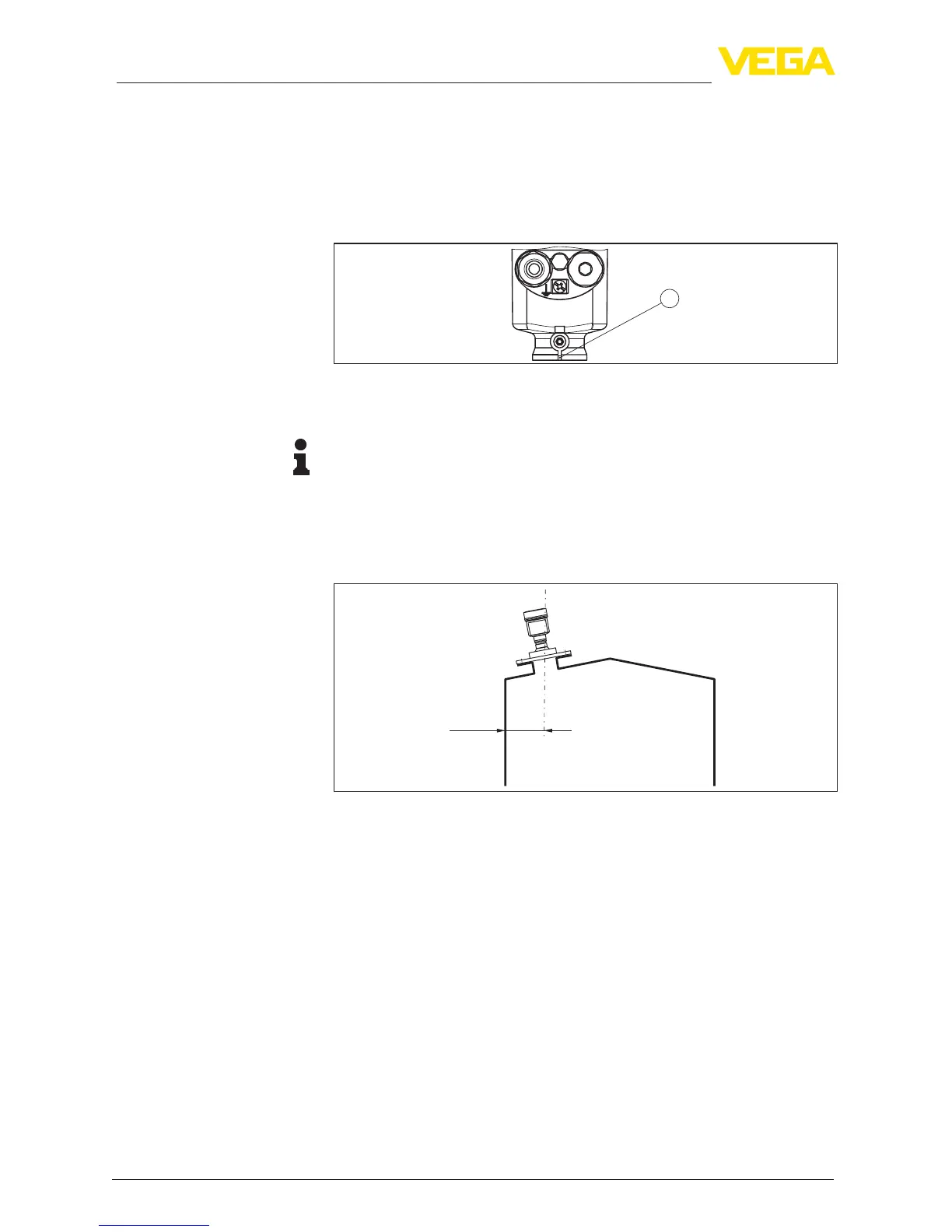
Mount the sensor at least 200 mm (7.874 in) away from the vessel
wall.
200 mm
(7.87
")
Fig. 9: Mounting the radar sensor on the vessel top
If you cannot maintain this distance, you should carry out a false
signal suppression during setup. This applies particularly if buildup on
the vessel wall is expected. In such cases, we recommend repeating
the false signal suppression at a later date with existing buildup.
Theinstrumentshouldnotbemountedtooclosetotheinowing
medium, as the radar signal could be disrupted.
Silowithllingfromtop
Theoptimalmountingpositionisoppositethellingaperture.Toavoid
heavysoiling,thedistancetoanylterordustexhaustershouldbeas
large as possible.
Polarisation
Installation position
Inowingmedium