32
5 Connecting to the bus system
VEGAPULS 69 • Foundation Fieldbus
47251-EN-160815
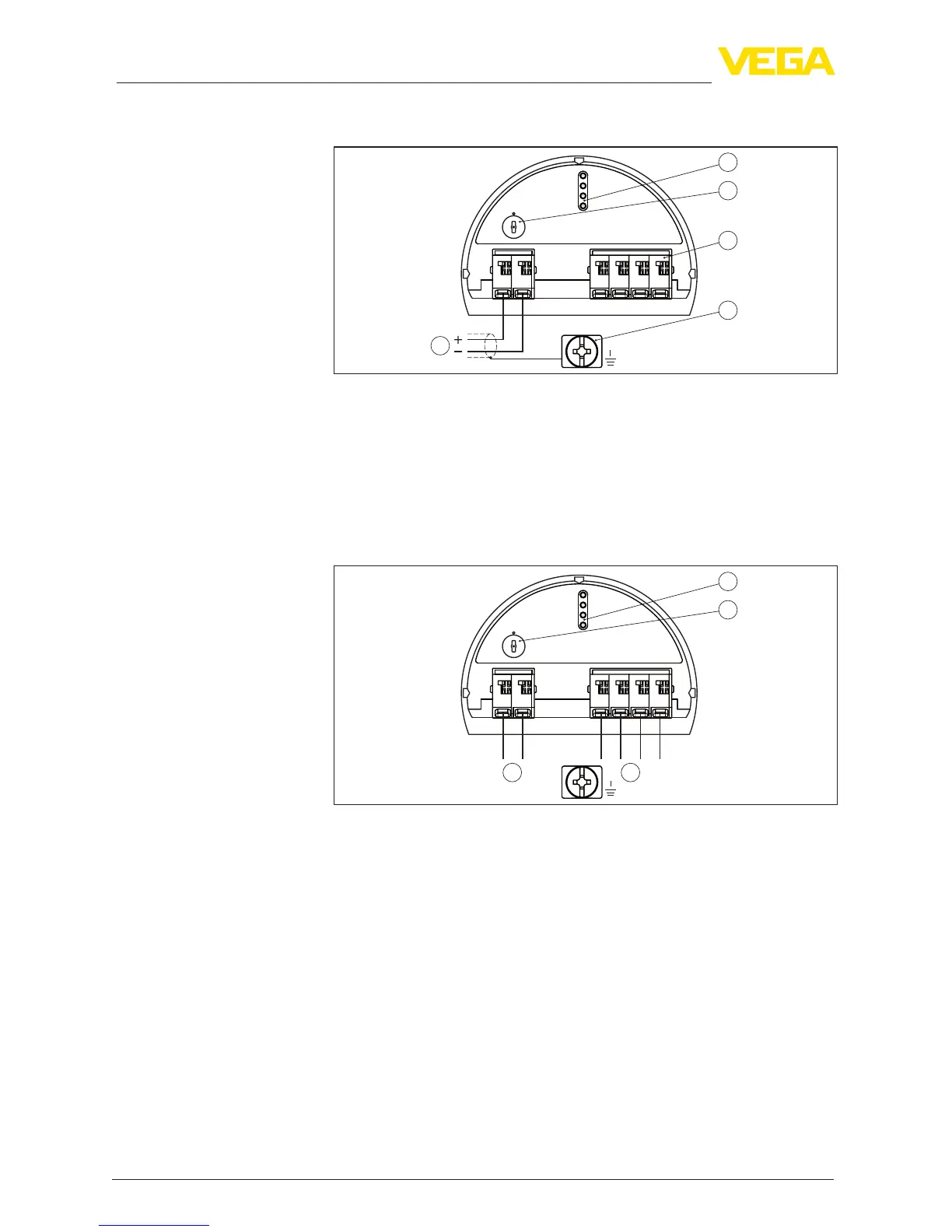
5.3 Wiring plan, single chamber housing
1
2
( )
(-)
1
5
0
1
0
1
+
678
Bus
3
4
5
Fig.27:Electronicsandterminalcompartment,singlechamberhousing
1 Voltage supply, signal output
2 Contactpinsforthedisplayandadjustmentmoduleorinterfaceadapter
3 Simulation switch ("1" = mode for simulation release)
4 For external display and adjustment unit
5 Groundterminalforconnectionofthecablescreen
5.4 Wiring plan, double chamber housing
5
0
1
0
1
+
678
Bus
3
1
2
( )
(-)
11
Fig.28:Electronicscompartment,doublechamberhousing
1 Internal connection to the terminal compartment
2 Contactpinsforthedisplayandadjustmentmoduleorinterfaceadapter
3 Simulation switch ("1" = mode for simulation release)
Electronics and terminal
compartment
Electronics compartment