26
4 Mounting
VEGAPULS 69 • Foundation Fieldbus
47251-EN-160815
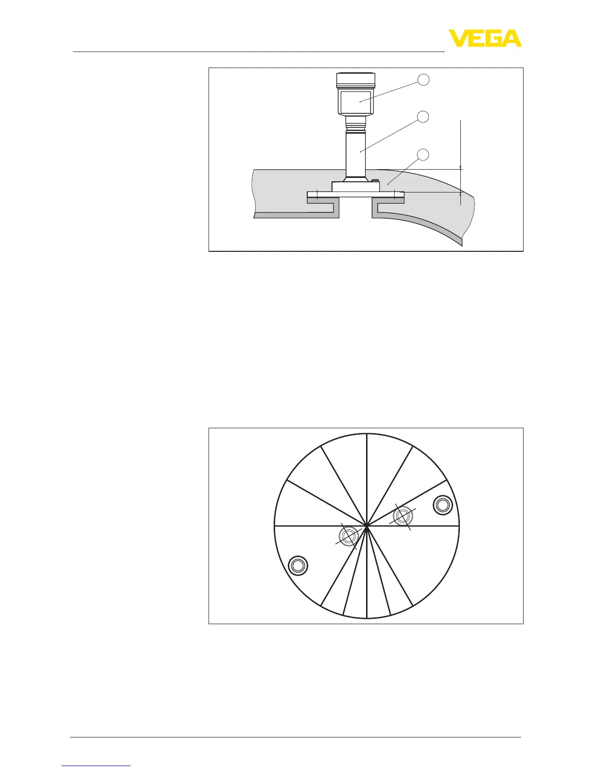
max. 50 mm
(1.97")
1
2
3
Fig. 19: Mounting the instrument on insulated vessels.
1 Electronicshousing
2 Spacer
3 Vessel insulation
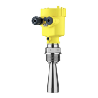
Thewallsofmultiple-chambersilosareoftenmadeofprolematerial,
e.g.prolesheeting,toensuretherequiredstability.Iftheradarsen-
sor is mounted very close to a heavily structured vessel wall, substan-
tialinterferingreectionscanbegenerated.Thusthesensorshould
be mounted at the largest possible distance from the separating wall.
The best mounting location is on the outer wall of the silo, with the
sensor pointing towards the discharge opening in the silo centre. This
can be accomplished, for example, with the mounting strap.
Fig. 20: Installation and orientation in multiple chamber silos
Mounting in multiple
chamber silo


 To Next Page