High Definition LiDAR Sensor
Velodyne LiDAR, Inc.
©
2019
Appendix B: Connector Pin outs
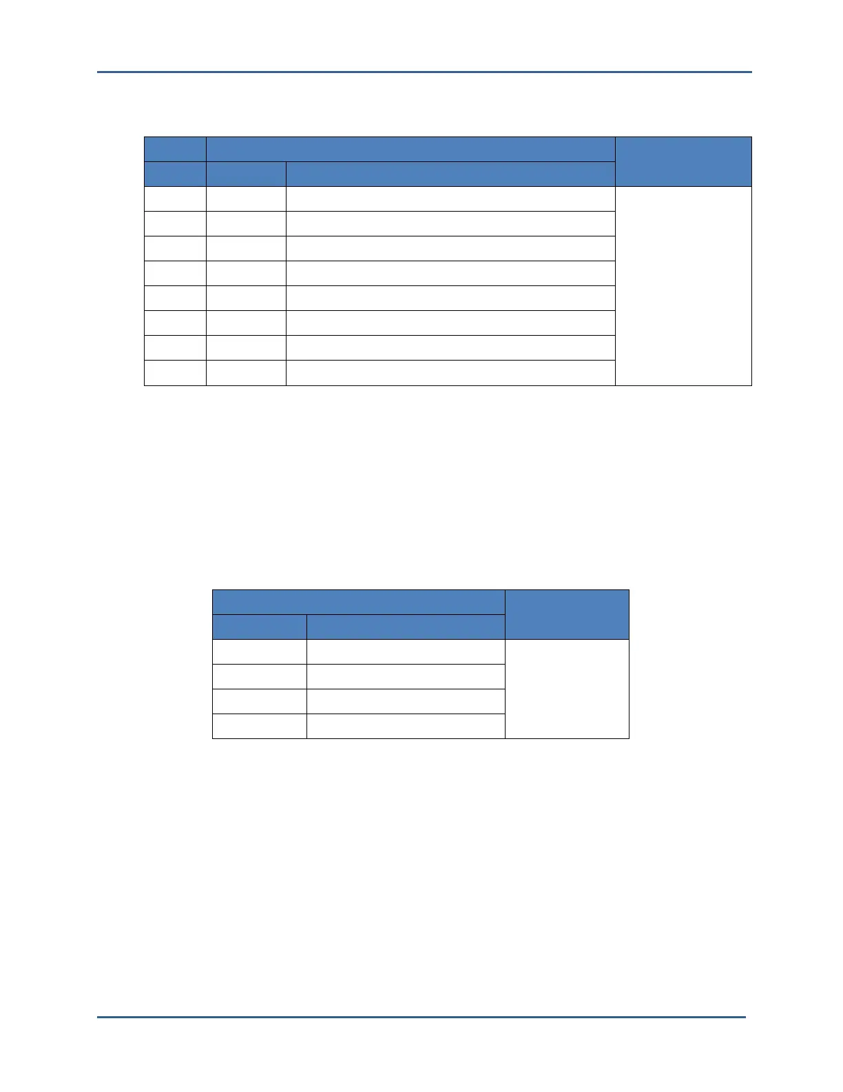
Power, Serial & GPS Connector
Power, Serial & GPS Connector J1
Cable
Mating
Connector
Pin
Color Description
1
Red Supply voltage (+12 to +32 VDC Input)
Deutsch DT06-8S
2
Black Ground
3
Green PPS Input (Optional - from GPS)
4
Orange NOT USED
5
Blue GPS Ground (optional – from GPS)
6
White GPS Serial (optional – NMEA message from GPS)
7
Black Serial RX (Control messages from user’s computer)
8
Red Serial Ground
All data inputs (PPS, GPS Serial, and Serial RX) are considered active in the logical 1 state.
• Logical “1”: Voltage must be greater than 2 V and no more than 25 V.
• Logical “0”: Voltage must be less than 1.3 V
Ethernet Connector
The Ethernet connection is used for output of data only, but requires the cable to be full duplex for
hardware handshaking.
Ethernet Connector J2
Cable
Mating
Connector
Pin Number
Description
1
Ethernet TX+
M12 D-CODED
2
Ethernet RX+
3
Ethernet TX-
4
Ethernet RX-
 Loading...