14 | Page
Version 00
© Verder Liquids B.V
Ds500, Ds500+ Operating manual
Original instructions (en)
– Press to stop the pump
also
– Hold during boot to update rmware from USB device,
see 10.3.6.6 Software
Start
– Press to start the pump
also
– Holdduringboottostarttouchcalibrationprocedure,
see 10.1.1 Touch calibration.
Discharge point (out)
– Fluid outlet, M24 threaded connector to be used with tube
connection kit (supplied)
Breather point
– Pressure relief in the unlikely event of a hose burst - do
not obstruct!
Itisrecommendedthatthehosetailconnectionisttedto
aidwithanyuidcapture.
Cartridge
– Replaceable cartridge which facilitates non-contact uid
transfer.
Suction point (in)
– Fluid inlet, M24 threaded connector to be used with tube
connection kit (supplied).
Cartridge lock
– Engages and locks the cartridge in position.
External control input
M12, 5 pin, B coded socket
– Digitalcontrol:Run/stop,externalcontact
– 4-20mA speed control input
External control output
M12, 5 pin, A coded socket
– Digital control: Alarm, pump running conditions
– 4-20mA speed indication output
Mains input
– Pre-tted mains cable with moulded plug (not user
serviceable) for connection to a suitable mains supply 100-
240 VAC.
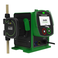
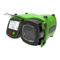
7.3.2 Rear
Figure 5. - Ds500 rear
Table 11. -
Item Description Item Description
1 PAT connection
earth point (M4)
2 USB port
3 IP66 vent
Layout (rear)
Portable Appliance Test (PAT) connection earth point
– Earth connection used only for testing.
USB port
– CoveredUSBportforrmwareupdates.
NOTE: in order to maintain IP integrity, the USB cover
mustbettedwhentheportisnotinuse.
Vent
– Ensure there is unobstructed free space around the unit
so as to maintain optimum air ow and heat dissipation.
Ensure recommended ambient temperature is within
Verder recommendations - see 6.4.1 Ambient.
1
2
3