23 | Page
Version 00
© Verder Liquids B.V
Ds500, Ds500+ Operating manual
Original instructions (en)
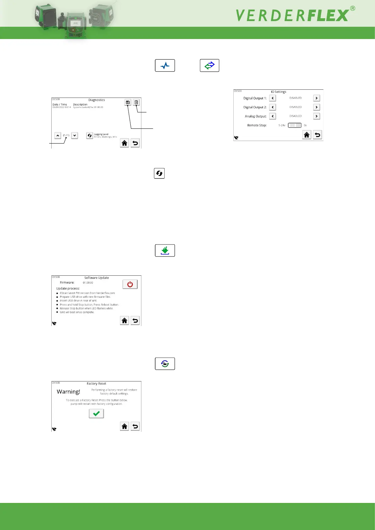
10.3.6.5 Diagnostics
This screen shows a log of all errors and warnings since the
last factory reset:
Figure 33. - Diagnostics
The information can be ltered by type; Errors - Errors and
Warnings - Errors, Warnings and Info by pressing the
button.
This log can also be transferred to a connected USB storage
deviceasaCSVle.
The log can be deleted to aid on-screen viewing (log is
retained in memory).
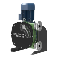
10.3.6.6 Software
Usethisscreentoupdatethesoftware/rmwareofthepumpby
following the on-screen instructions:
Figure 34. - Software Update
NOTE:Thermwarelesmustbestoredintherootdirectory
of a FAT32 format USB removable device.
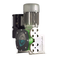
10.3.6.7 Factory Reset
Use this screen to perform a factory reset of the unit:
Figure 35. - Factory Reset
PINentryrequiredtoconrmfactoryreset(default1111).
Warning - ALL settings will be deleted and the defaults will be
restored.
Delete log
Save log
Next/previous
page
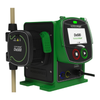
10.3.7 I/O settings (Ds500+ only)
This screen provides the options for conguring the external
control Input / Output signals:
Figure 36. - I/O Settings
10.3.7.8 Digital Output 1
Disabled, Run Status, General Alarm, Fluid Level Low Alarm,
Cartridge Issue
10.3.7.9 Digital Output 2
As above
10.3.7.10 Analog Output
Input Matched
Current present on the input pin will also be present on the
output pin, e.g., 4mA input = 4mA output.
Can be used for daisy chaining units.
Full Scale
4-20mA output derived from current motor speed, e.g.,
0 rpm motor speed = 4mA output
65rpm motor speed = 20mA output
10.3.7.11 Remote Stop
Used to set the voltage on the Remote Stop input which triggers
a stop.
The ‘Supply’ output can be used with this pin or an external
voltage (e.g., 5-24V from a PLC) can be used.
If 5-24V is selected, the pump will run when the run/stop input
is connected to the GND/0V and stop when connected to the
positive voltage.
If 0V is selected, connect the run/stop to GND/0V to stop the
pump. To start the pump it should be connected to a positive
voltage.