16 | Page
Version 00
© Verder Liquids B.V
Ds500, Ds500+ Operating manual
Original instructions (en)
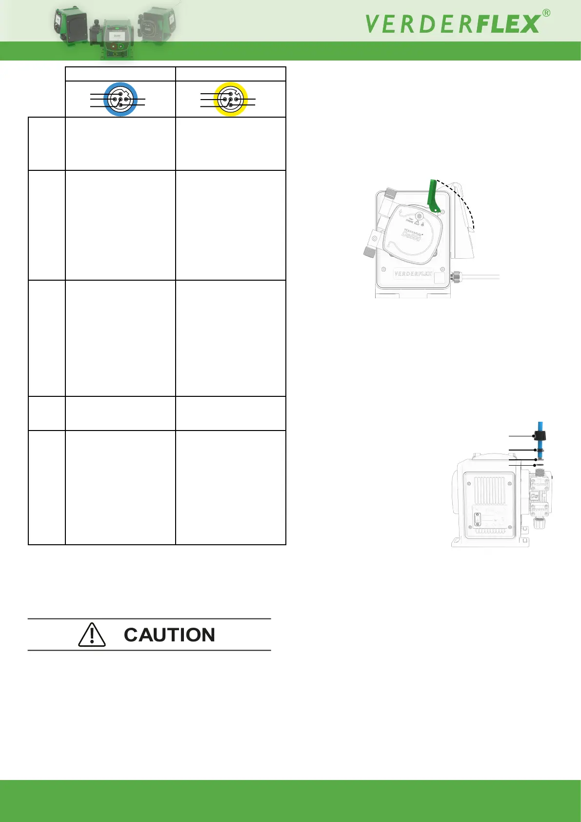
Input Output
1
Brown
Run/ stop
5-30VDC, referenced to
GND
Digital Output 1 (open
collector)
User programmable
output - see 10.3.7
2
White
External contact
5-30VDC, referenced to
GND.
40-1000ms pulse,
5-24VDC.
Use with a normally open
switch for manual dosing
or a PLC output for
automation.
Digital Output 2 (open
collector)
User programmable
output - see 10.3.7
3
Blue
4-20mAspeed/ow
control input
120Ω input impedance.
Maxcurrent40mA.
Referenced to GND,
polarity protected.
4-20mAspeed/ow
indication output
Current source output
referenced to GND.
Requiresaload
resistance 100 to 330Ω
for optimal results. Use
a >100Ω resistor if using
with a DVM.
4
Black
GND (0V) GND (0V)
5
Grey
Reserved for future use.
5-30VDC, referenced to
GND.
Supply
Protected 5V output. Can
supply up to 20mA. Can
be used with a resistor to
setRun/Stoporexternal
contact inputs high or can
supply low current loads
connected to either digital
output.
Table 12. - Externalcontrolpinout
Colourreferstotypicalwirecolourinreadilyavailableleads.Pleaseconrmthese
colours before connection as there is no guarantee all manufacturers will follow
this convention.
Donotconnectmultipleunitsinseries;ifpumpsaretobedaisy
chained then use the ‘Input Matched’ function - see 10.3.7 I/O
settings (Ds500+ only).
See Section 16. Ds500+ external connections for wiring
example.
4
1
2
3
5
4
2
3
5
1
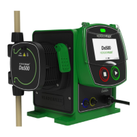
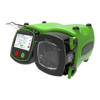
8.4 Fitting the Cartridge
NOTE: If the unit is already powered on - refer to 10.3.3
Cartridge information.
1. Lift the cartridge lock, as shown.
2. IInsertthecartridgeosetby20°,asshown:
Figure 6. - Fitting a cartridge
3. Rotatethecartridge20°CCWsothatit‘snaps’intoposition.
4. Push the cartridge lever down to secure the cartridge.
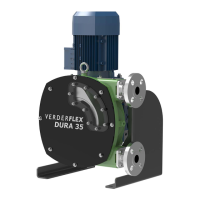
8.5 Connections to the Cartridge
Ensurethetubetobeconnectedispreparedwithasquare
end. In the following order, place on to the tube:
1. Port sealing nut
2. Clamp ring
(observe correct orientation)
3. Tubetting
4. O-ring
NOTE: Max internal diameter of
connecting tubes: 6.3mm.
Figure 7. - Cartridge connections
8.5.1 Removing the cartridge
Refer to Section 10.3.3 for correct procedure and to retain
cartridge data.
Locked
Unlocked
1
2
3
4