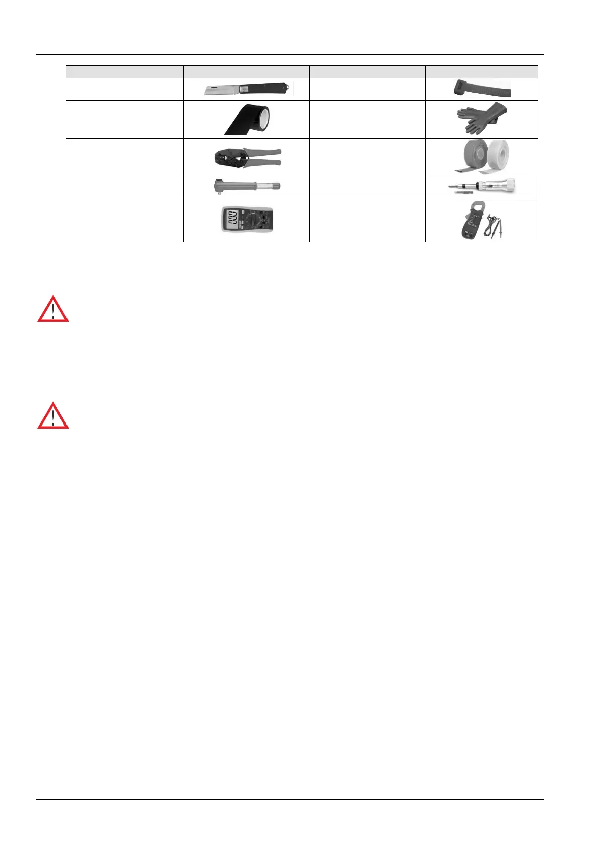
The tools mentioned in Table 2-1 are generic and commonplace; however, depending on various factors such as site
environment, cables, installation equipment, and on-site electrical connections these tools may vary in a real-time
scenario.
Ensure that the tools used in the installation, operation, and maintenance processes are insulated. This safety
measure is important for professionals and service personnel who work with this CR012 range of air conditioners.
2.3 Mechanical Installation
Proper installation is important to achieve optimal performance and prolong the product life. In this section, the
mechanical installation will be discussed in detail to help the personnel with the installation process.
Before proceeding with the mechanical installation, the following safety precautions need to be considered.
1. Prior to installation, ensure that the installation preparations have been read and implemented as per the
requirement. (Refer to section 2.2 on Installation Preparation for the details). Check if any modifications are
made to the plumbing, wiring, or ventilation facility before mounting the equipment. Once the installation
preparations are taken into consideration, move on to the next step in the installation process, and eventually
set up the system.
2. The CR012 cooling units are designed for split-floor installation. The indoor unit must be installed on the floor of
the equipment room or computer room. The outdoor unit must be installed outdoors or on the floor of the other
rooms as per the building architecture.
3. Industry-wide standards are followed for the selection, layout, and fixing of pipes.
4. Several factors such as pressure drop, compressor oil return, noise reduction, and vibration are considered
during the design and installation process.
5. Follow the design drawings strictly when installing the equipment. Reserve space as per the maintenance and
serviceability instructions in the previous chapter on Installation Preparation. The manufacturer’s engineering
dimension drawings must be taken as a reference while installing the equipment.
2.3.1 System arrangement during installation
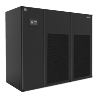
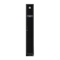
The general arrangement of the CR012 air cooled AC unit is depicted in Figure 2-6.




 To Next Page