3.3 Common Operational function examples
Following are the examples that depict the way the micro-controller works in almost all the options.
Example 1
This section depicts the process where the password is entered to access the Main Menu. After the unit is powered
on, the unit starts up.
Following are the step-by-step instructions that can need to be adhered and implemented to enter the Main menu.
1. Press the Enter button to enter the Password screen.
2. Next, press the Enter button again to highlight the input data field in the Password screen.
3. Press the Up and Down button to change the current password number.
4. Press the Enter button to confirm the password following which the Main Menu screen is populated on the
controller screen.
Example 2
This section depicts the process of changing parameters. The procedure is the same for almost all parameters. In this
example, the Hi Sup Temp in Alarm Stpt screen is used for illustration purposes: Following are the step-by-step
instructions of changing parameters for the Hi Sup Temp option:
1. Press the Up and Down button to move the cursor to the Alarm menu option in the Main Menu section.
2. To enter the Alarm Menu, press the Enter button.
3. Press the Up and Down button to move the cursor to the Alarm Set option on the Alarm Menu screen.
4. Press the Enter button to access the Alarm Set screen.
5. Press the Up and Down button to move the cursor to the Alarm Stpt on the Alarm Set Screen.
6. Press the Enter button to enter the Alarm Stpt screen.
7. Press the Enter button to highlight the parameter field of Hi Sup Temp.
8. In order to select the parameter option, scroll using the UP and Down buttons. Select/change the specific
Parameter.
9. Press the Enter button to confirm it following which the changes will take effect.
10. Press the Esc button to return to the previous menu screen.
On changing the parameters, the Enter button is not pressed, it means that the confirmation of the parameter change
has not taken place. Therefore, on non-confirmation, the original value of the Hi Sup Temp will be retained.
3.4 Main Screen
Once the air conditioner is powered on, the main page screen is displayed after 10 seconds of the startup delay as
depicted in Figure 3-3:
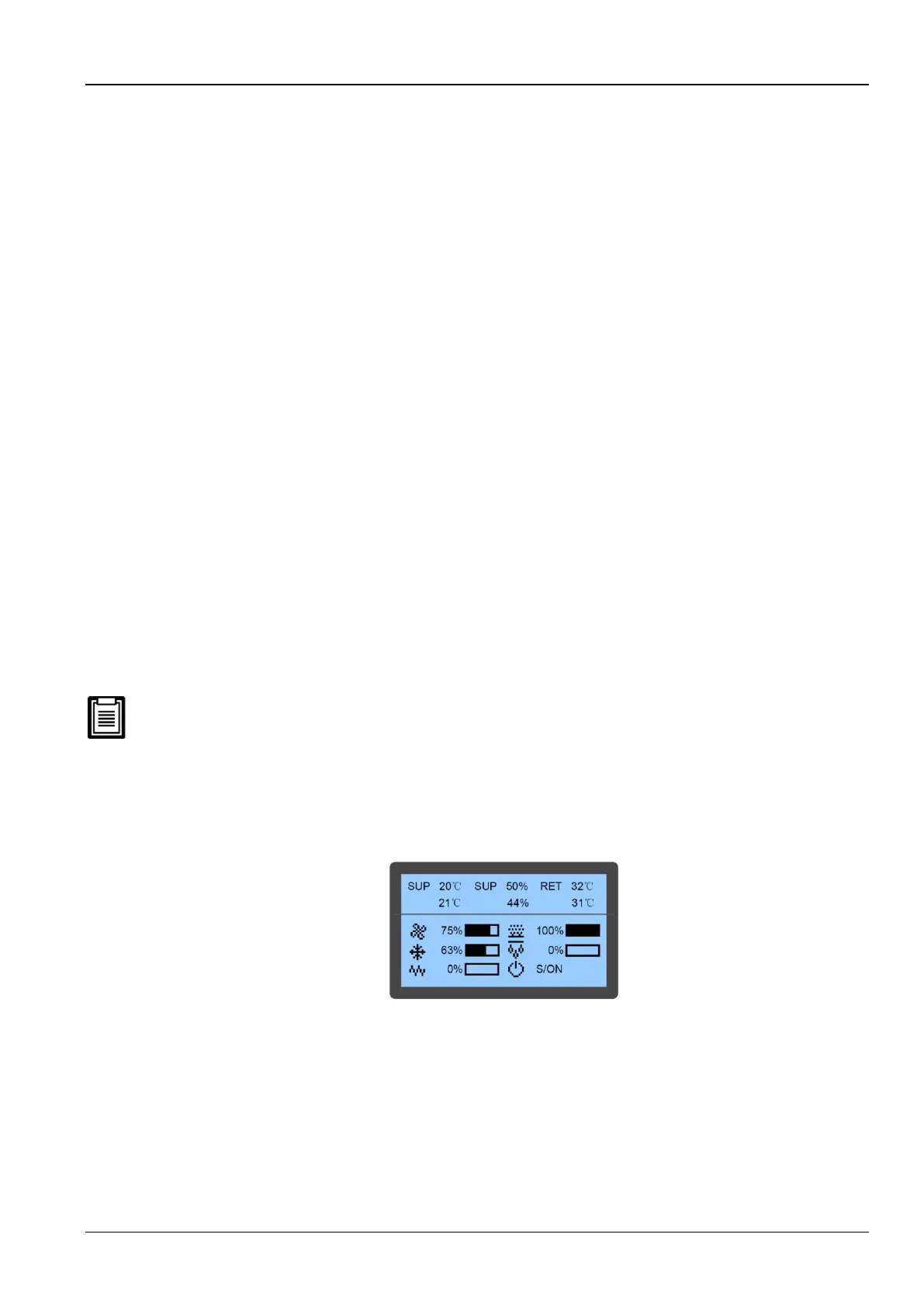
Figure 3-3 Main Screen
It displays the settings (20℃ as in fig. 3-3) and actual values (21℃ as in fig. 3-3) of the current air supply temperature
in the first queue, humidity in the second queue, and air return temperature in the third queue. When the compressor
mode or fan mode is set to Remote, the queue displays the remote temperature. In the lower part of the screen, it
displays the unit output status (fan, cooling, heating, dehumidifying, and humidifying) and unit operation status (off,
running, standby, and locked).
The icons on the main screen indicate the unit output status, unit property, and unit operating status. The icons and
their definitions are displayed in table 3-2.

 Loading...


