4. The power soft cable is a Y-type connection. If damaged, it has to be replaced immediately to eliminate the
dangers. The replacement procedure must be carried out by an authorized professional or experienced service
personnel.
5. The electrical installation and maintenance must be carried out by some authorized personnel or a trained
engineer well-versed with the inner workings of the electrical connection (For example, a service engineer from
the manufacturer’s side).
6. Prior to the wiring, a voltmeter must be used to measure the power supply voltage and ensure that the power
supply has been switched off.
7. Use screws, guide rails, or other modes to fix the device firmly during the installation process to avoid
movement or shaking during the start-up or operation mode.
8. For the air conditioner configured with EC fans, the unit power grid adheres to the TN or TT star connection
power distribution system. However, if there is a need to configure another type of power grid, contact the Vertiv
support team for the same.
9. An appropriate all –pole disconnection device must be supplied.
10. SCCR of the CR012 air cooled unit - 5 kA
11. The power soft cable should not be lighter than an ordinary PVC-sheathed according to the 53 line according to
GB5023.1(idt IEC60277)
12. For appliance of outdoor, the power cable should be not lighter than Chloroprene rubber sheathed flexible cord
which is 57 line according to IEC 60245.
2.4.3 Connecting cables of the Indoor unit
This section deals with the different types of connections related to the indoor unit, namely–
1. Electrical port location of the indoor unit
2. Connecting the Power cables of the indoor unit
3. Connecting the Control cables
4. Connecting the Solenoid valve of the Pipe extension kit (Optional)
5. Teamwork Control
Electrical Port location of the indoor unit
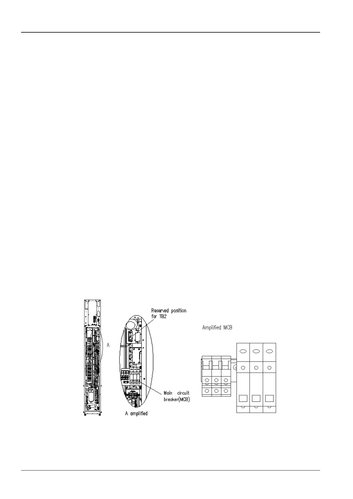
Open the back door of the indoor unit following which the specific layout and locations of the low voltage components
can be viewed as depicted in Figure 2-26. For detailed layout information on low voltage components, refer to the
labels on the cabinets and units.
Figure 2-26 Unit electrical control box and cable connection



 To Next Page