Connecting the Power cable of the Indoor unit
The specific location of the power port of the indoor unit is depicted in Figure 2-26. Connect the supply terminals L1-
L3, N, and PE to their respective counterparts of the external power supply respectively.
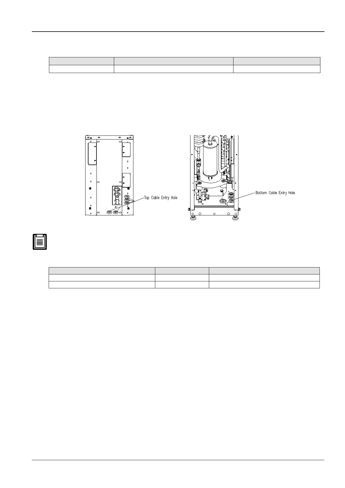
Fix the input cables to the cable clamp, located on the inner side panel of the unit. The top cable entry hole and
bottom cable entry hole as depicted in Figure 2-27.
For the cable specifications, refer to the full-load current (FLA) described in the Table 2-14.
Figure 2-27 Top and bottom cable entry holes
The cable sizes must strictly meet and adhere to the local wiring regulations and protocols as it supersedes every
type of connection.
Table 2-15 Full load current (Unit A)
Connecting the Control cables
The location of the terminal block for cable connections in the site is depicted in Figure 2-26. The amplified view of
the terminals is shown in Figure 2-28.
 Loading...


