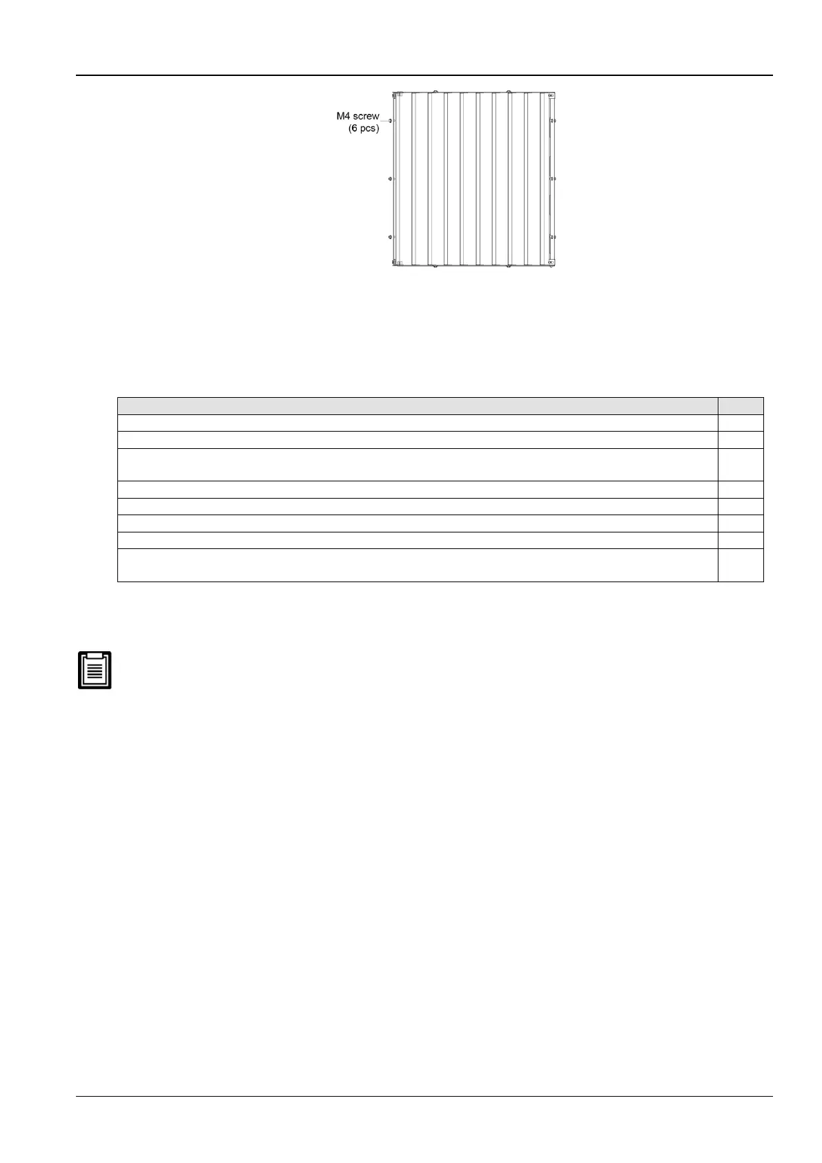
Figure 2-25 Fixed mode of the supply air baffle
2.3.7 Checklist for completed mechanical installation
Following are the points in the checklist (Refer Table 2-13) that need to be verified and confirmed to ensure that the
mechanical installation was implemented successfully:
Table 2-13
After installation, foreign materials in and around the equipment are removed (such as shipping materials, construction
materials, tools, and so on)
2.4 Electrical Installation
In this chapter, the electrical installation of the CR012 air cooled units is explained in-depth to help users with the
various tasks which include the cable connections of the indoor unit apart from the checklist.
The Liebert CR012 air conditioners are professional devices used in industrial, commercial, or other professional
occasions. It is not tailored for the general public. The total rating power is larger than 1 kW and is in with the
IEC61000-3-12 standard. A port of less than a 350-short-circuit requires is required between the user power and the
grid. Permission is required from the power supply department to ensure that the air conditioner is connected to a
power no less than 350 circuit ratio.
2.4.1 On-site Wire connections
Following are the wires to have to be connected in/on the site:
1. Power cable and control cabinet of the indoor unit
2. Solenoid valve cable of the pipe extension kit (an optional requirement)
3. Input and Output control the cable of the unit
2.4.2 Installation Notes
1. The connections of all the power cables, control cables, and ground cables should be in compliance with the
local and national electrical regulations.
2. Observe the unit nameplate for the full load current. The cables sizes must meet the conditions as specified in
the local wiring protocols and rules.
3. Mains supply requirement: (380 to 415) V ± 10%; 50 Hz/60-Hz, 3N-
 Loading...


