Figure 2-28
The connection personnel must take anti-static measures before connecting the control cables.
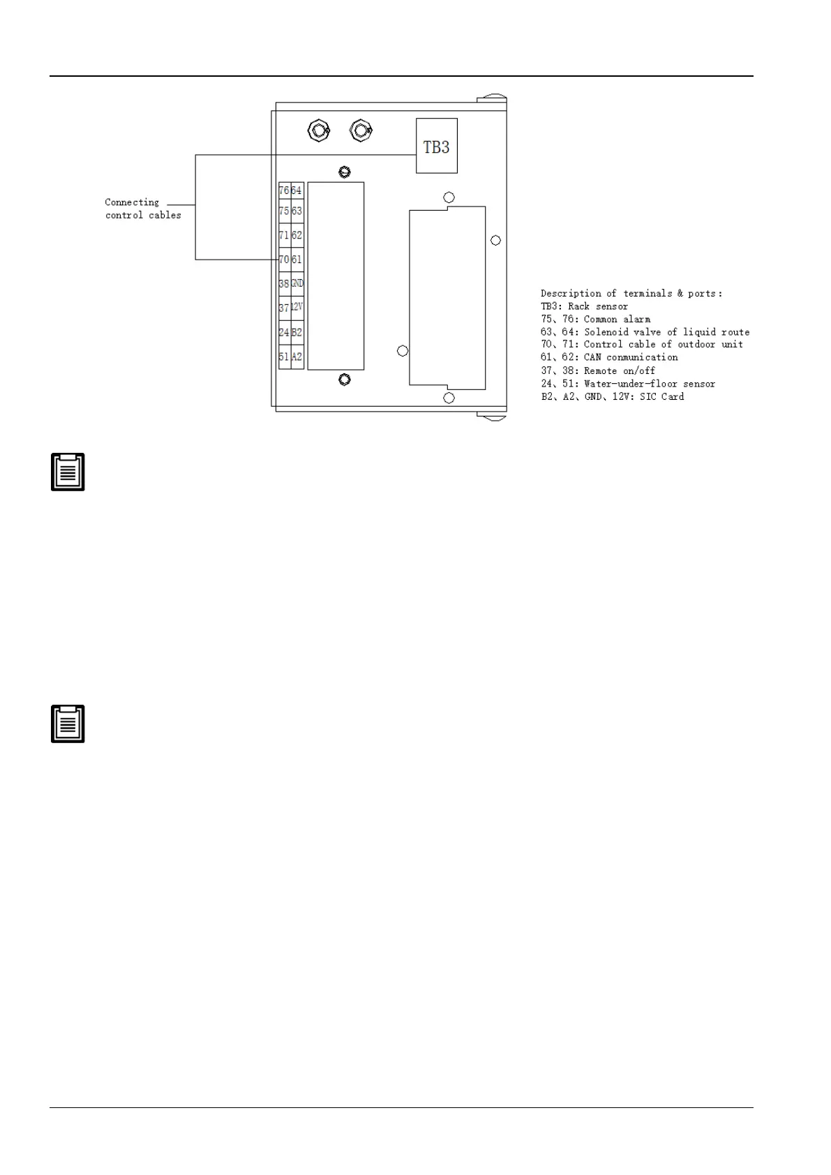
Water-under-floor sensor
If a water-under-floor sensor is equipped, connect one end of the sensor to terminal 51# and the other end to
common terminal 24#.
Each unit can be connected with multiple sensors in parallel, but there would be only one water-underfloor alarm.
SIC card
If a SIC card is equipped, connect A#, B#, GND#, and 12# on the SIC card to the respective counterparts on the
terminal block.
Also, if a Modbus card is equipped, connect A#, B#, on the Modbus card to the counterparts on the terminal block
respectively.
Either SIC or Modbus card can be equipped based on the user requirement. Refer to Appendix 1 Circuit Diagram for
in-depth information.
Rack sensor
Each unit can be connected with a maximum of 10 temperature sensors. It is recommended that the sensors be
located in front of the heat loads to achieve the most precise temperature. If the sensors are connected in series
(refer Figure 2-29), each temperature sensor monitors the temperature of air entering each rack, and the read
temperature value is used to control unit operation. The standard location of the sensor is 1.5m height. Therefore, the
sensors should be placed in positions as depicted in Figure 2-29, or the devices cannot operate appropriately.
 Loading...


