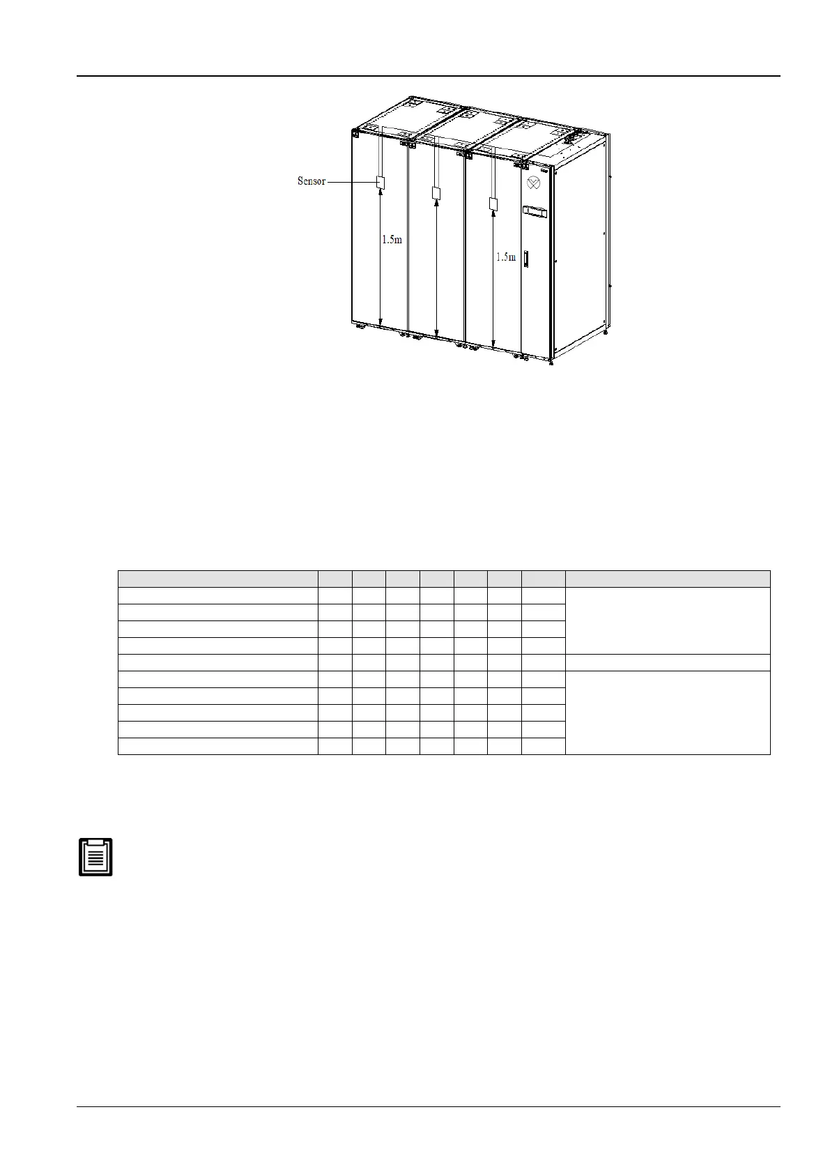
Figure 2-29 Layout of rack sensors
Following is the procedure to connect sensors for Liebert CR012 models:
1. Insert the connector of the rack temperature sensor in the TB3 point. On connecting the cable, route the cable
through the top or bottom of the unit following which it should be connected to the first sensor. Connect the first
sensor to the second sensor. Thus, the sensors are connected in a chain.
2. Fix the temperature in front of the hottest source inside the rack. Do not fix it in front of the empty sub-rack. Affix
the sensor on the rack surface using the magnets provided in the kit. The sensor must be fixed in a position that
is mostly short of cool air.
Rack temperature sensor IRM-S01 address settings are depicted in the table 2-16.
Table 2-16
Remote Shutdown
As depicted in Figure 2-28, terminals 37# and 38# can be connected to the remote shutdown switch. The terminals
must be shorted before delivery. If a remote shutdown signal is to be connected, remove the short-connect cable.
Closing the terminals 37# and 38# will shut down the unit.
Control signals of the outdoor unit
Terminals 70# & 71# are the control signal input terminals of the outdoor unit. Their On and Off state is the same as
that of the compressor 2#. They can be connected to the compression rotation speed control terminals on the control
board of the outdoor unit. However, connecting them is an option depending on the requirement.
External Common Alarm
Terminals 75# and 76# can be connected to the external common alarms. They generate signals to external alarm
devices such as an alarm indicator. When the critical alarm occurs, the contact will be closed to trigger remote alarms,
send signals to the building management system, or dial the paging system automatically.
 Loading...


