Vertiv™ | Liebert® DM | User Manual 58
Electrical Installation
• Overflow detection (custom 3 terminal)
If the unit is equipped with an overflow detection board, connect the overflow detection board in the accessory to the
control terminals (07 kW/12 kW main control board J21-7, J21-8, 17 kW/22 kW/27 kW control terminal
TB-51 and TB-24 before starting-up). The overflow detection board should have the metal contacts facing down and placed
on the bottom plate below the evaporator tray.
If the terminal is open, the unit will stop giving outputs. The terminals have been shorted before delivery.
If the control cables need to be connected at site, remove the short cables and connect the outer controller to the remote
On/O terminals respectively.
• The customer terminal (control terminal) can connect with any alarm signal except for the system.
• Any outer alarm signal with NO dry contact can be connected with customer terminal. After the outer alarm
signal is connected, user should set the corresponding customer alarm information in micro-processing
controller.
• If no alarm signal is connected, the input state of the customer terminal is the same as that of setting. If an
outer alarm is generated, the input state is dierent from the setting.
• The system will generate an audible alarm and LCD screen on micro-processing controller will display the
corresponding alarm information. If a computer using Vertiv host monitoring software is connected, the
alarm will be displayed on it too.
• General alarm terminal
The general alarm relay, connected with (pin 19 and pin 20 (07 kW/12 kW), pin 75 and pin 76 (17 kW/22 kW/
27 kW)) (see Figure 3-11) of the terminal block, has a set of NO dry contact, and it can also be set to NC through software.
When a major alarm is generated, the contact is closed. This can be used to send a remote alarm, sending signals to the
Building Management System (BMS) or dialing the paging system automatically.
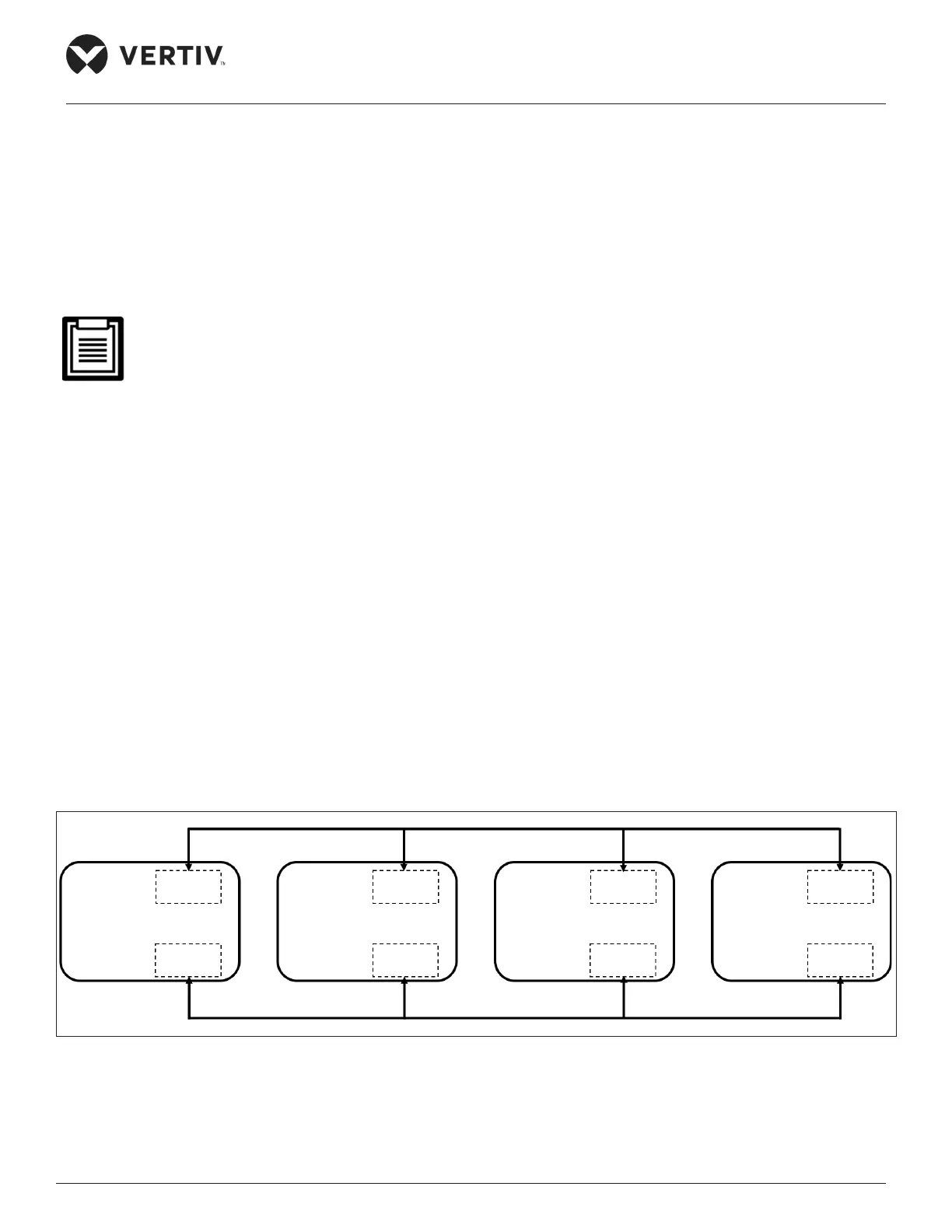
• Teamwork control terminal
The Liebert® DM air conditioners support the teamwork control function of up to 4 units. If user needs to use the teamwork
control function, then connect the main control boards J20-1 and J20-2 between the units in series for 07/12kW shown
in Figure 3-12 and connect the teamwork control terminals 73 and 74 between the units in series for 17/22/27kW shown in
Figure 3-13. After the teamwork control unit is cabled, as given in Table 3-2, set the teamwork control unit DIP switch on the
printed circuit board (see Figure 3-10) to complete the address setting.
Figure 3-12 Connection Diagram of Teamwork Control Terminal (07/12 kW)
Main Unit1 J20-1
SW3 switch address 00
J27 J20-2
Main Unit2 J20-1
SW3 switch address 01
J27 J20-2
Main Unit3 J20-1
SW3 switch address 02
J27 J20-2
Main Unit4 J20-1
SW3 switch address 03
J27 J20-2