Digit Description
Digit 20 = Sensors
0 = None
S = Smoke sensor
H = High-temperature sensor
F = Smoke and High-temperature sensors
C = Compressor-overload sensors
A = Compressor, high-temperature sensors
D = Compressor, smoke sensors
K = Compressor, high-temperature, smoke sensors
Digit 21 = Packaging
P = Domestic
C = Export
Digit 22-24 = Factory Configuration Number
Digit 25 = Configuration Code
A = 1
S = SFA
Table 2.2 DSE Model-number Digit Definitions (continued)
2.2 Component Location
The unit component locations are described in the submittal documents included in the Submittal
Drawings on page93.
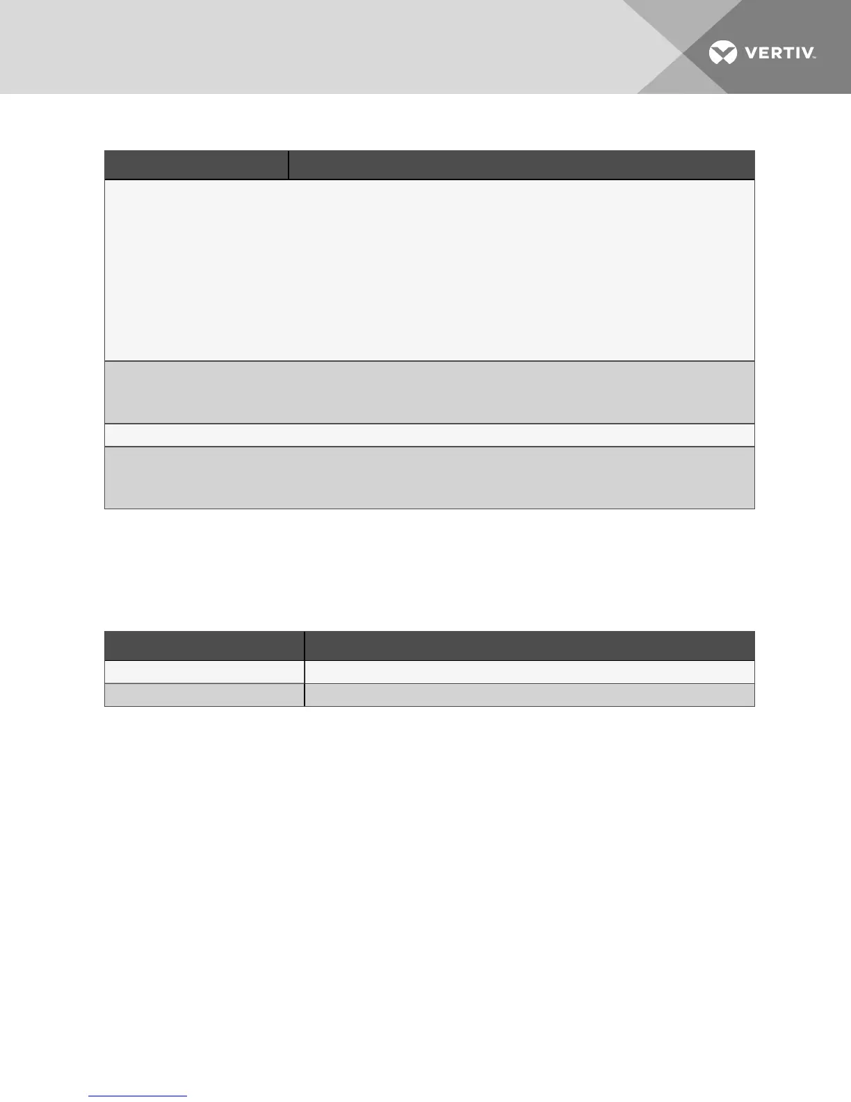
The following table lists the relevant documents by number and title.
Document Number Title
DPN003452 Component Location, Typical, Downflow Models, DA050–DA165
DPN003451 Component Location, Typical, Upflow Models, DA080–DA085
Table 2.3 Component-location Drawings
2.3 Cooling Configurations
NOTE: All field-installed piping must comply with applicable local, state and federal codes. Refer to
Piping, for detailed information.
2 Nomenclature and Components 13