• A pure dry nitrogen flow of 1-3 ft
3
/min (0.5-1.5 l/s) inside the pipe during brazing is sufficient to
displace the air. Control the flow using a suitable measuring device.
• Ensure that the tubing surfaces to be brazed are clean and that all burrs have been removed
from the ends of the tubes.
• Ensure that all loose material has been cleaned from inside the tubing before brazing.
• Protect all refrigerant line components within 18in. (460mm) of the brazing site by wrapping
them with a wet cloth or with a suitable heat-sink compound.
• Isolate piping from building using vibration-isolating supports.
• Condensers with receivers cannot be installed below the evaporator. The maximum height of
the condenser above the evaporator is 60ft (18.3m).
Consult the factory before installing units, condensers, and receivers outside these parameters.
• Consult factory if piping run exceeds 300ft (91m) actual length or 450ft(137.2m) equivalent
length.
• Install traps on hot-gas (discharge) lines at the base of vertical risers over 5ft(1.5m) and every
20ft(6m) for vertical rises over 25 ft (7.6m), then install a trap in 20-ft (6-m) increments or
evenly-divided over the vertical rise.
• Pitch horizontal hot-gas piping down at a minimum rate of 1/2in.per 10ft (42mm per 10m) so
that gravity will aid in moving oil in the direction of refrigerant/oil flow.
• Keep piping clean and dry, especially on units with R-410A refrigerant.
• Avoid piping runs through noise-sensitive areas.
• Do not run piping directly in front of discharge air stream.
• Refrigerant oil – do not mix oil types (see Compressor Oil on page70).
Refer to ASHRAE Refrigeration Handbook for general, good-practice refrigeration piping. The indoor
cooling unit has a factory-installed high-pressure safety switch in the high side refrigerant circuit. A
fusible plug kit is installed in each Liebert® DSE receiver.
NOTE: All indoor and outdoor field refrigerant piping must be insulated 1/2 in. minimum. All outdoor
insulation must be UV and ozone resistant.
• Refer to Refrigerant Line Sizes and Equivalent Lengths below, for recommended refrigerant
piping sizes based on equivalent pipe lengths.
• Refer to Refrigerant Charge Requirements for Air-cooled Systems on the facing page, for the
refrigerant-charge requirements of the system.
• Refer to Charging Air-cooled Systems on page41, for charging information.
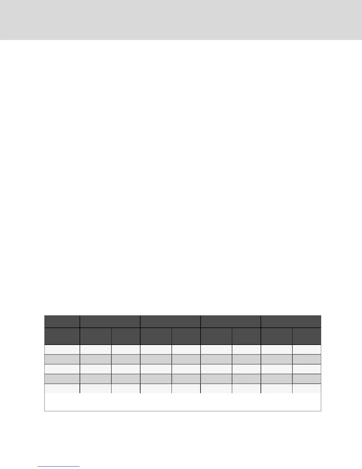
5.2.2 Refrigerant Line Sizes and Equivalent Lengths
Model DA050 DA080 and DA085 DA125 DA150 and DA165
Equivalent
Length
Hot Gas
Line, in.
Liquid
Line, in.
Hot Gas
Line, in.
Liquid
Line, in.
Hot Gas
Line, in.
Liquid
Line, in.
Hot Gas
Line, in.
Liquid
Line, in.
50 ft (15 m) 1-1/8 7/8 1-1/8 7/8 1-3/8 7/8 1-3/8 7/8
100 ft (30 m) 1-1/8 7/8 1-1/8 7/8 1-3/8 7/8 1-3/8 1-1/8
150 ft (45 m) 1-1/8 7/8 1-1/8 7/8 1-3/8 7/8 1-3/8 1-1/8
300 ft (91 m) 1-1/8 7/8 1-1/8 7/8 1-3/8 7/8 1-3/8 1-1/8
450 ft (137 m)* 1-1/8 7/8 1-1/8 7/8 1-3/8 7/8 1-3/8 1-1/8
*Consult factory when actual pipe length between condenser/EconoPhase and Liebert DSE unit will exceed 300 ft (91 m).
Source: DPN000788. Rev. 11
Table 5.4 Recommended Refrigerant Line Sizes, OD Copper
Vertiv | Liebert® DSE™ Installer/User Guide
36