3.3 Air-distribution Considerations for Upflow Units
For in-room applications with supply and return grilles, several feet of clearance must be maintained at
the intake and discharge of the unit.
NOTE: Drain traps are qualified to a return duct static of negative 1.5 i.w.g. (-1.5i.w.g).
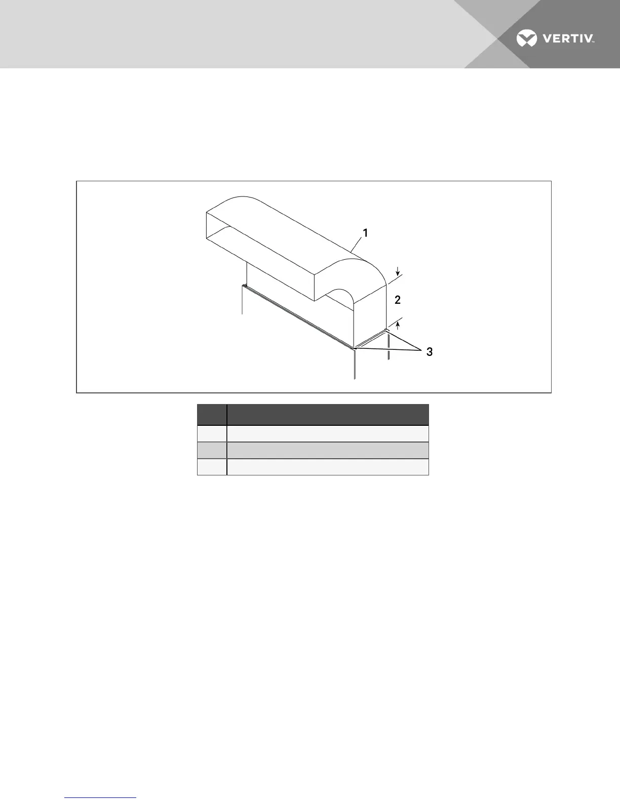
Figure 3.2 Upflow ducting configurations for EC fans for DA080 and DA085
Item Description
1 Typical ducting. May run to either side.
2 Straight section muse be 2.5 times the depth of blower.
3 Ducting only attached to flanges onprovidedplenum.
NOTE: Follow standard practices in all ductwork.
3.4 Connections and System Setup
• The unit requires a drain, which must comply with all applicable codes. This drain line may
contain boiling water. See Field-installed, Gravity-fed Drain Line Requirements on page32, for
details.
• Three-phase electrical service is required for all models. Electrical service must conform to
national and local electrical codes. See equipment nameplate for details.
• Plan the routing of wiring, piping and ductwork to the unit. Refer to the appropriate piping
connection location drawings, piping schematics, and electrical-connection drawings for your
system in Submittal Drawings on page93.
• If seismic requirements apply, consult your Vertiv representative for information about a
seismic-rated floor stand.
NOTE: Seal openings around piping and electrical connection to prevent air leakage. Failure to do so
could reduce the unit’s cooling performance.
The DSE controls superheat with an electronic expansion valve (EEV). The EEV controller adjusts the
orifice based on suction pressure and temperature. The EEV control will drive the valve to maintain the
superheat setpoint, set in the Liebert® iCOM, using a Proportional, Integral, Derivative (PID) routine. The
PID control values are set at the factory for most applications. These default values PID will allow stable
superheat control of the unit.
3 Pre-installation PreparationandGuidelines 19