5 PIPING AND REFRIGERANT REQUIREMENTS
All fluid and refrigeration connections to the unit, with the exception of the condensate drain, are sweat
copper. Factory-installed piping brackets must not be removed. Field-installed piping must be installed in
accordance with local codes and must be properly assembled, supported, isolated and insulated. Avoid
piping runs through noise-sensitive areas, such as office walls and conference rooms.
Refer to specific text and detailed diagrams in this manual for other unit-specific piping requirements.
All piping below the elevated floor must be located so that it offers the least resistance to air flow. Careful
planning of the piping layout under the raised floor is required to prevent the air flow from being blocked.
When installing piping on the subfloor, we recommend that the pipes be mounted in a horizontal plane
rather than stacked one above the other. Whenever possible, the pipes should be run parallel to the air
flow.
The following pipe connections are required:
• A drain line from the unit.
• A drain line from the secondary drain pan (if applicable).
• A water-supply line to the optional humidifier (if applicable).
• Refrigerant piping connections between the evaporator unit, the condensing unit, and the
optional economizer unit. See Refrigerant Piping and Charging on page35.
The pipe connection locations, piping general arrangement and schematics are described in the
submittal documents included in the Submittal Drawings on page93.
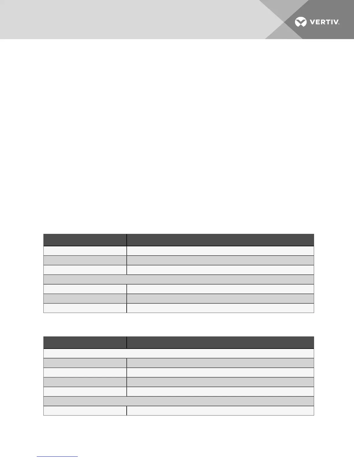
The following tables list the relevant documents by number and title.
Document Number Title
DPN002615 Piping Schematic, DA050, DA080 and DA085 with MC Condenser
DPN002340 Piping Schematic, DA125, DA150 and DA165 with MC Condenser
DPN004476 Piping Schematic, DA125, DA150 and DA165 with MCV Condenser
Liebert® MCCondenser and EconoPhase Pump Locations
DPN003994 Considerations for mounting MC Condenser/EconoPhase Above or at Same Level as DSE
DPN003552 Typical arrangement for single-circuit system
DPN002324 Typical arrangement for dual-circuit system
Table 5.1 Piping General-arrangment Drawings
Document Number Title
Downflow Units
DPN003531 Connection Locations, DA050
DPN004080 Connection Locations, DA080 and DA085
DPN002312 Connection Locations, DA125
DPN004037 Connection Locations, DA150 and DA165
Upflow Units
DPN002951 Connection Locations, DA080U and DA085U
Table 5.2 Piping Connection Drawings
5 Piping and Refrigerant Requirements 31