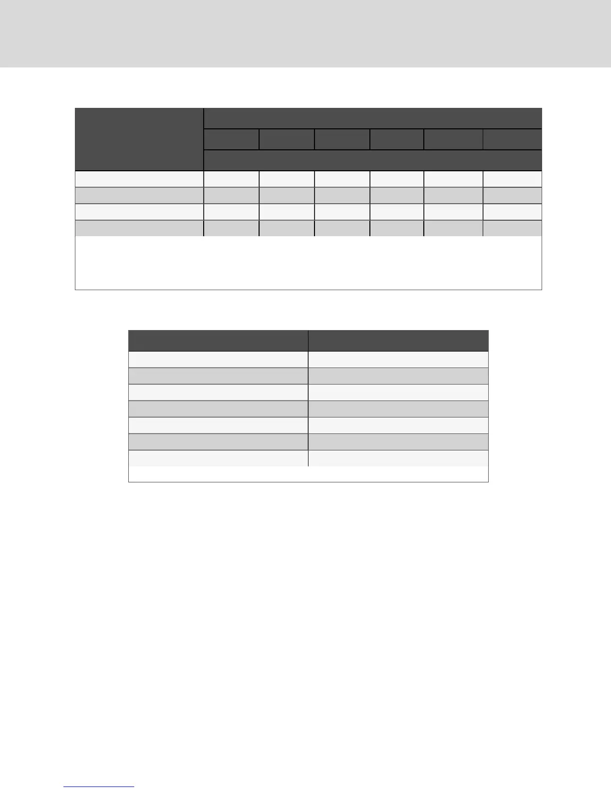
Refrigerant System Charge
Per Circuit, lb (kg) *
Model
DA050 DA080 DA085 DA125 DA150 DA165
Additional Oil Required Per Circuit, oz (ml)
170 (77.1) 57 (1690) 57 (1690) 57 (1690) 43 (1270) 114 (3370) 114 (3370)
180 (81.6) 61 (1800) 61 (1800) 61 (1800) 46 (1360) 122 (3610) 122 (3610)
190 (86.2) 65 (1920) 65 (1920) 65 (1920) 49 (1450) 130 (3840) 130 (3840)
200 (90.7) 69 (2040) 69 (2040) 69 (2040) 52 (1540) 138 (4080) 138 (4080)
*System Charge = indoor unit + condenser + refrigerant receiver + refrigerant lines.
For system charges over 200 lb. (90.7kg), consult your Vertiv representative.
See 10.7 on page70 for the recommended oil for the system.
Source:DPN003950 Rev. 5
Table 5.9 Additional Oil Required per Refrigerant Charge (continued)
Pipe diameter, in. Oil volume, oz (ml)
1/2 0.2 (5.9)
5/8 0.4 (11.8)
3/4 0.6 (17.7)
7/8 0.9 (26.6)
1-1/8 1.8 (53.2)
1-3/8 3.3 (97.6)
1-5/8 5.5 (162.7)
Source: DPN003950, Rev. 3
Table 5.10 Volume of Oil in Standard-form Trap by Pipe Diameter
5.2.5 Evacuation, Leak-testing, and Charging Air-cooled Systems withReceivers
Two discharge lines and two liquid lines (one discharge line and one liquid line for DA050 models)must be
field-installed between the indoor unit and the outdoor condenser. See DPN002615 and DPN002340 in
Appendix C: on page93. for additional field-installed piping needed at the condenser.
NOTE: Keep the evaporator unit, EconoPhase, and condenser closed with their factory charge of dry
nitrogen while all field piping is installed. Keep the field piping clean and dry during installation. Do not
allow it to stand open to the atmosphere. When all the field interconnecting piping is in place, vent each
outdoor unit’s dry nitrogen charge and connect to the field piping. Finally, vent the evaporator unit's
dry nitrogen charge and make its piping connection last. Follow all proper brazing practices, including a
dry nitrogen purge to maintain system cleanliness. The condenser connection pipes must be wrapped
with a wet cloth to keep the pressure and temperature sensors cool during any brazing.
Evacuation and Leak-testing Air-cooled Systems
For proper leak-check and evacuation, you must open all system valves and account for all check valves.
NOTE: The system includes a factory-installed check valve and an additional downstream Schrader
valve with core in the compressor discharge line. Proper evacuation of the condenser side of the
compressor can be accomplished only using the downstream Schrader valve. See the appropriate
piping schematic for your system in Submittal Drawings on page93.
Vertiv | Liebert® DSE™ Installer/User Guide
40