REV : 1
REV DATE : 6/18
DPN004388
Page :3 /4
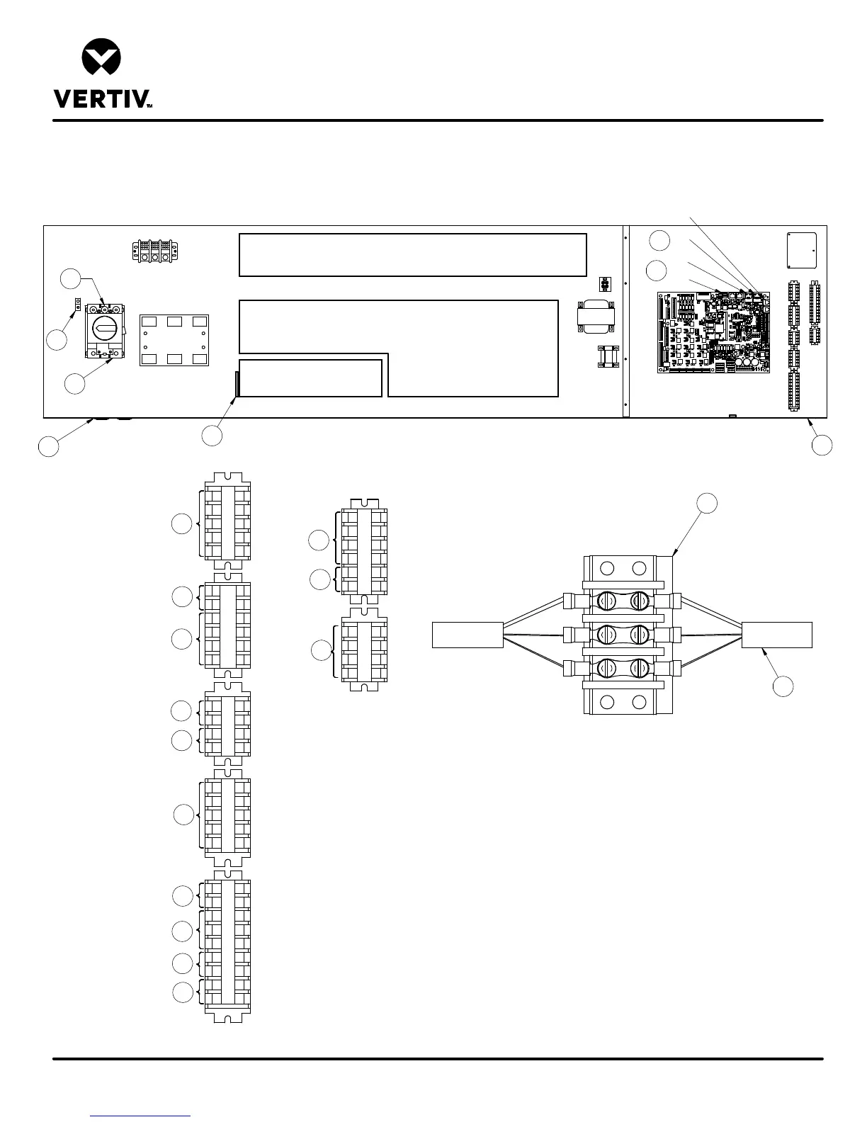
DA125, DA150 & DA165 DOWNFLOW MODELS
Form No.: DPN001040_REV4
LIEBERT DSE
24
50
51
55
56
37C
37
38
38C
37B
38B
75
76
94
95
97
82
83
88
89
80
81
91
92
93
58
59
70
71
84
85
11
12
96
230
41
42
43
44
5
2
1
9
4
3
A
A
Note: Typical orientation of components shown.
Component location varies by option and unit size.
OVERCURRENT PROTECTION DEVICES
OVERLOADS
CONTACTORS AND RELAYS
LOW VOLT SECTION
F
B
C
D
E
H
F
6
7
8
14
15
16
17
19
20
21
22
B
C
D
E
SH49-1
49-3
10
11
H
4
Item 11 Installation Conditions
1. Follow all local installation codes.
2. Do not run CAN cables in same conduit, raceway, or
chase as high voltage wires (120-600V).
3.Separate high volt wires from CAN wires by 12 inches.
ELECTRICAL FIELD CONNECTIONS
G
TB3
P74
P67
P64
G
18
23
24